COM-KIT Interface Board Schematics and Layout
Overview
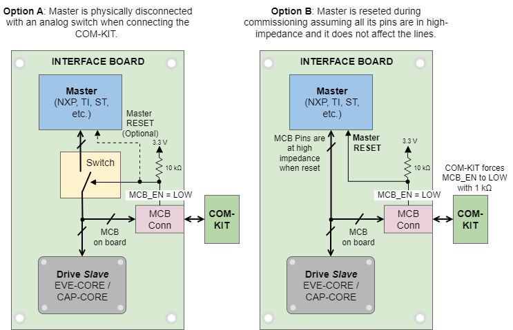
Since the COM-KIT acts as a master it cannot be connected directly to the MCB as it would collide with the Master, causing communication problems and even electrical damage. In order to perform this connection there 2 alternatives.
Option A. Analog switch. (recommended): physically disconnect the master when you connect the COM-KIT using an analog switch or analog multiplexer. The analog switch must allow ≥50 MHz, have low capacitance < 10 pF, and low resistance < 20 Ω to avoid distortion or reflections of SPI signals.
Option B. Master reset. Connect the MCB_EN pin to the master reset (assuming is active low). When the COM-KIT is connected forces the line to low, resetting the master assuming it leaves all its I/O pins in high-impedance mode. This is the simplest, lowest cost, and lowest board space option. The main drawback is that a T stub may be formed on the SPI lines, with the parasitic impedance of the pins can cause communications problems. Do this option if PCB tracks are kept within < 20 cm length, and the master does leave all pins at high impedance with a pin capacitance < 10 pF.
Schematic
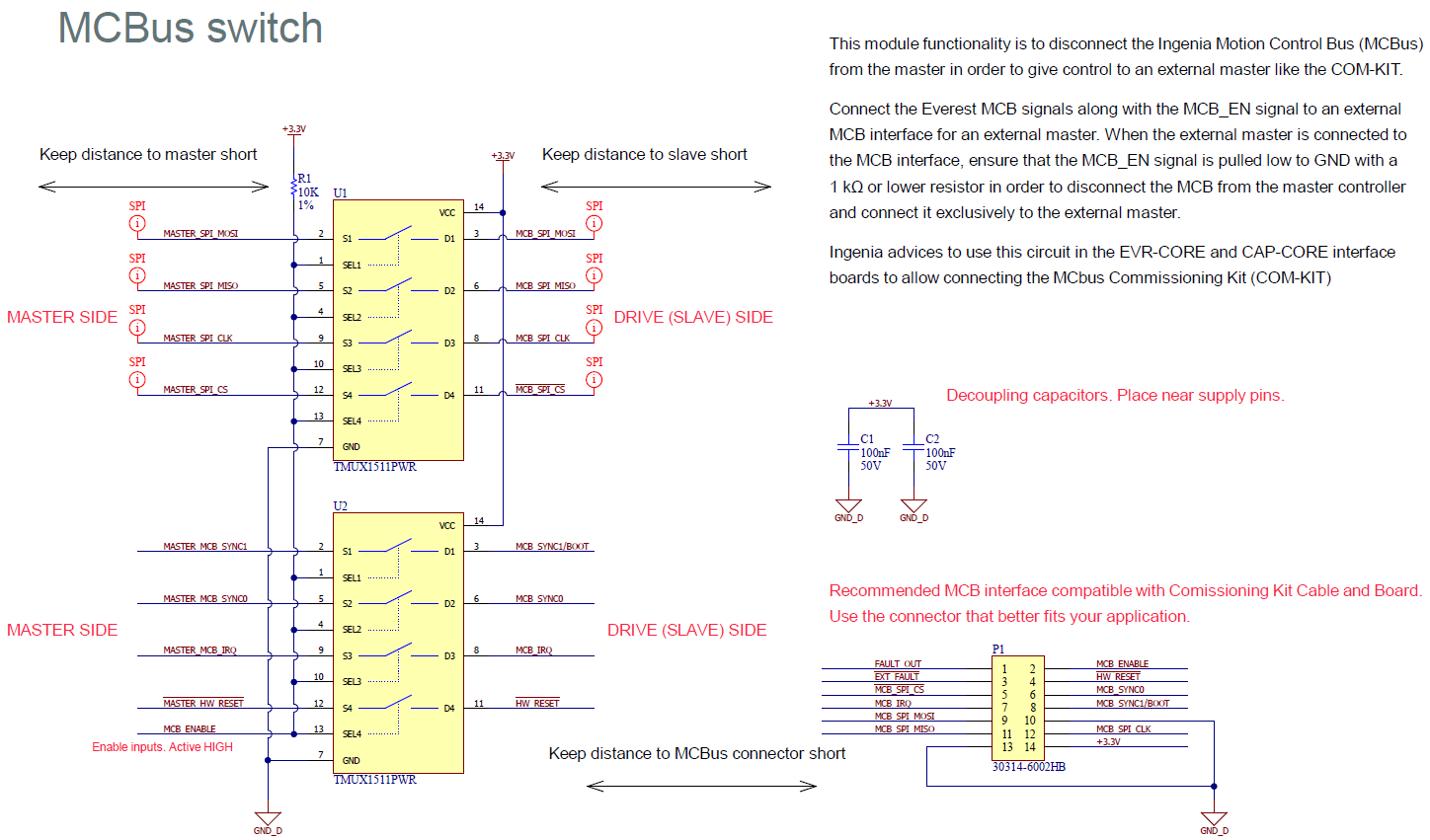
The Commissioning board needs the 8 MCB signals CLK, MISO, MOSI, \CS, SYNC0, SYNC1, IRQ, and \HW_RESET signal to be able to communicate with the Everest/Capitan Core. All those signals must be disconnected from the master controller and connected exclusively to the Commissioning kit board to avoid having two masters driving the bus.
About this solution
Notice that this solution is designed to be simple, cost-effective, and easy to manufacture. Other solutions from those presented here may also be valid, and even be more suitable for different approaches or design constraints.
The proposed solution consists of adding two analog switches (or SPST multiplexers) in the interface board in order to disconnect the master controller when the Commissioning Kit Board is connected. The default status of the multiplexer would be the master controller and the switching of the multiplexer would be controlled by a signal called MCB_EN. Whenever the Commissioning Kit Board is connected to the Everest/Capitan Core interface board, the multiplexer disconnects the MCB bus from the master. A 10 kΩ resistor pull-up is required in the MCB_EN signal at the interface board.
Although it is not mandatory, it is recommended to reset the master also when the commissioning kit is connected using the MCB_EN pin. This prevents confusion during the commissioning.
The following are some recommended analog switches. Choose according to your size, technology, or cost requirements.
Part Number | Manufacturer | On resistance | Pin Capacitance | Footprint | Features |
|---|---|---|---|---|---|
TMUX1511PWR | Texas Instruments | 4.5 Ω | 2.5 pF | 14-TSSOP | Power-off protection avoids issues either when COM-KIT or the slave is off. |
TMUX1511RSVR | 16-UFQFN | ||||
74LVC4066BQ,115 | Nexperia | 10 Ω | 8 pF | 14-VFQFN | - |
74LVC4066PW,118 | 14-TSSOP | - | |||
74LVC4066D,118 | 14-SO | - |
See the recommended schematic next:
Download the schematics of the proposed solution in PDF and Altium format here:
M_IUO005_MCB_multiplexer.SchDoc
Layout Recommendations
The layout of the MCB SPI fast signals should be done carefully following high-speed PCB design recommendations. The other signals are less critical but should also be routed carefully.
Try to reduce the distance between the master and the slave, the connector should not create a stub longer than 25 mm.
Please take into account the following points with the trace layout of the 3 fast SPI signals: MCB_SPI_MOSI, MCB_SPI_MISO, MCB_SPI_CLK.
Do not ever route these signals close to the motor phases or switching nodes of DC/DCs. Keep a safe > 15 mm distance to switching noise.
Ensure they have a good GND return on all its length on the PCB. Route them as strip lines, if possible microstrip for longer distances is also recommended.
Keep line impedances between 60 Ω and 150 Ω.
Avoid T stubs and acute angles.
Minimize crosstalk to other signals by reducing parallel coupled lenght.
Consider adding 0 Ω ~ 47 Ω series termination resistors at the end of the fast lines as a provision to minimize reflections in case communication issues arise.