Operation
The following diagram shows the main Summit servo drives architecture regarding drive operation:
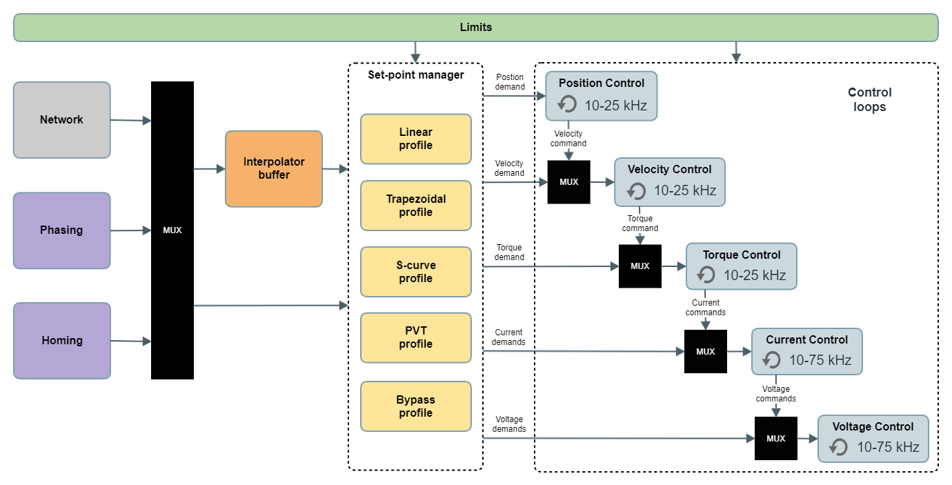
Network, Phasing and Homing blocks are the different sources of set-points. The network is always the main command source, however, when a phasing sequence or a homing is executed, the set-points from the network are ignored until the process finishes.
Inside the set-point manager, only one profile can be active at a time. The set-point manager is also responsible for delivering data from the interpolator buffer to the profiles.
Inside the control loops, all the loops are connected in cascade. So if a control block is enabled, all the other blocks to the right are active too.
Example
If velocity control is active, torque, current and voltage control blocks will be active too, whereas position control may be active or not.
Control loops rate (execution frequency) can be adjusted depending on the selected power stage frequency.
The allowed values for the control loop rates are product-dependent.
Modes of operation
Modes of operation are selected using register operation mode and current mode is displayed in operation mode display.
The interconnection of the interpolator buffer, the set-point manager and control loops blocks result in a different mode of operation. These modes of operation are classified in:
Basic modes
Cyclic modes
Profiler modes
Interpolated modes
There is an extra operation mode which includes the Homing block: Homing mode.
Users have complete control of the active mode of operation except when the phasing process is executed.
Basic modes
These modes are composed only by control loops (bypass profile from set-point manager):
Position mode (P)
Velocity mode (V)
Torque mode (T)
Current mode (C)
Voltage mode
These modes take directly the information from the network set-point at the control loop rate.
These modes are useful for tuning purposes or in cases where the update rate of the main device/instance set points is near to the control loops rate.
There is not an equivalent mode of operation from CiA402 / DS402 profiles for these modes.
Cyclic modes
These modes are composed by control loops and the linear profile:
Cyclic Synchronous Position (CSP) - Compatible with CSP from CiA402 / DS402
Cyclic Synchronous Velocity (CSV) - Compatible with CSV from CiA402 / DS402
Cyclic Synchronous Torque (CST) - Compatible with CST from CiA402 / DS402
Cyclic Synchronous Current (CSC)
These modes require to know the update rate of the network set points. This rate is compared with the internal control loops rate and the linear profile interpolates values between set-points. This allows smoother movements and relaxed timings from the main device/instance's side.
These modes are useful when the main device/instance is the one that generates the system profile, because the included by the drive does not fulfill the application requirements or because the profile involves multiple-axis that must be synchronized. Usually, a proper set-point update rate for these modes are 1 - 2 kHz.
Profiler modes
These modes are composed by control loops and trapezoidal or S-curve profiles:
Profile Position (PP) - Compatible with PP from CiA402 / DS402
S-curve Profile Position (SPP)
Profile Velocity (PV) - Compatible with PP from CiA402 / DS402
These modes use a configurable trapezoidal or S-curve profiles that generate all the required demand values from a single set-point value.
These modes are useful when the profile option inside the drive can fulfill the application requirements or/and the main device/instance capabilities do not allow generate an external profile at the required rate and determinism.
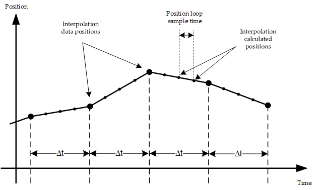
Interpolated modes
These modes are composed of control loops, all the available profiles, and the interpolator buffer:
Interpolated position mode (IP) - Uses linear profile
Position, velocity and time (PVT) - Uses 5th-degree polynomials
These modes use the interpolator buffer to store a sequence of set-points. The drive injects these set-points into its control loops at a configurable update rate.
These modes are useful when the profile has to be generated by the main device/instance but it is not able to transfer the set-point at a deterministic update rate. It sends bursts of set-points and gives the drive the responsibility to inject them at the proper time.
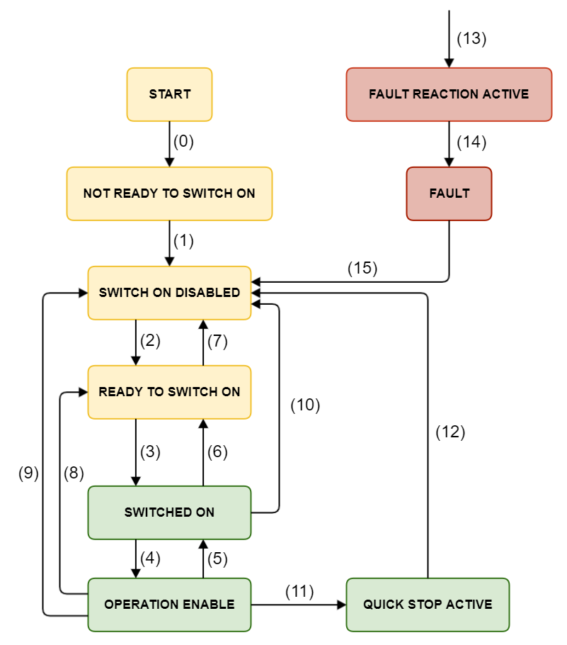
State machine
To operate with the previous modes of operation the drive implements a subsection of the CiA402 profile to standardize the drive states during configuration and operation. This state machine is composed of the next states:
The following table indicates which functionalities can be activated in every state.
Function | Not ready to switch on | Switch on disabled | Ready to switch on | Switched on | Operation enabled | Quick stop active | Fault reaction active | Fault |
|---|---|---|---|---|---|---|---|---|
Brake applied | Yes | Yes | Yes | Yes | No | No | No | Yes |
Drive function enabled | No | No | No | No | Yes | Yes | Yes | No |
Configuration allowed | Yes | Yes | Yes | Yes | No | No | No | Yes |
The controller supports the following events and actions.
Commands are sent using the control word register.
Transition | Event | Action |
|---|---|---|
0 | Automatic transition after power-on or reset application. | Drive device self-test and/or self initialization is performed. |
1 | Automatic transition after initialization. | Communications are activated. |
2 | Shutdown command received | None. |
3 | Switch on command received | The high-level power is switched on. |
4 | Enable operation command received | The drive function is enabled. |
5 | Disable operation command received | The drive function is disabled. |
6 | Shutdown command received | The high-level power is switched off. |
7 | Quick stop or disable voltage command received | None. |
8 | Shutdown command received | The drive function is disabled, and the high-level power is switched off. |
9 | Disable voltage command received | The drive function is disabled, and the high-level power is switched off. |
10 | Disable voltage or quick stop command received | The high-level power is switched off. |
11 | Quick stop command received | The quick stop function is started. |
12 | Automatic transition when the quick stop function is completed or disable voltage command is received | The drive function is disabled, and the high-level power is switched off. |
13 | Fault condition. | The configured fault reaction function is executed. |
14 | Automatic transition. | The drive function is disabled, and the high-level power is switched off. |
15 | Fault reset command received | A reset of the fault condition is carried out, if no fault exists currently on the drive. |
When the drive function is disabled, no energy will be supplied to the motor. Targets or set-points (torque, velocity, position) in that situation are not processed.