Installation
Unboxing
When unboxing the drive please ensure the following:
Remove it from the bag carefully.
Check that there is no visible physical damage. If any, report it immediately to the carrier.
Check the part number of the drive on the side label.
Installation Safety Requirements
The drive has live circuits that can be touched and entail a risk of electric shock (Protective Class 0), as well as a risk of thermal injury. It must be mounted on a closed electrical operating area to which access is restricted to skilled or instructed personnel. This enclosure, cabinet, protection, or case should have a minimum Index of Protection of IP3X. To ensure electrical safety it is also important that the environment is clean from conductive pollution or condensation when the drive is powered (Pollution degree 2).
 | WARNING HOT SURFACES! |
The drive and motor can become hot and cause severe burns. If any of the user-accessible surfaces exceeds 70 ºC, a hot-surface signal must be added. This is the responsibility of the installer. | |
 | DANGER, ELECTRIC SHOCK! |
Power and motor pins have live voltages which can exceed 50 V which can cause electric shock! Perform installation procedures without voltage. Ensure the drive is mounted on a closed electrical operating area which protects against direct contact. |
The drive may be operated without enclosure and protection against electric shock when it is supplied at Extra Low Voltage (ELV), ≤ 50 V.
Mounting the Drive to a Heatsink or Cooling Plate
The drive has 4x M2.5 threaded holes with a max. thread depth of 4.5 mm for assembling the Capitan XCR to a cooling plate or heatsink. See Dimensions section for further details. Assembling the drive correctly is essential to:
Provide a conduction heat dissipation path. Please see the Thermal and Power Specifications section in the Product Description chapter to determine your heat dissipation needs.
Ensure electrical conduction between the drive and Protective Earth, chassis, or the motor enclosure. This is strongly recommended for EMC and electrical safety.
Secure the drive in place to prevent any damage.
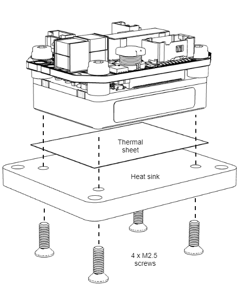
Back Installation
The preferred way to assemble the drive is from the back using a thermal interface tape and 4 x M2.5 screws. Thermal tapes and materials offer a clean and repetitive way to improve the heat transfer from the drive to the heat sink. There are several thermal interface alternatives, some suggested part numbers are T-Global Technology LI98-1140-27-0.25, Berquist Bond-Ply 100 series, t-Global Technology GT30S, or copper conductive tape CCH-18-101-0100. To install the drive, follow these steps:
Ensure the bottom surface of the drive and the heatsink are clean and dry. Isopropyl alcohol (isopropanol) applied with a lint-free wipe or swab should be adequate for removing surface contamination such as dust or fingerprints. Do not use “denatured alcohol” or glass cleaners which often contain oily components. Allow the surface to dry for some minutes before applying the tape. More aggressive solvents (such as acetone, methyl ethyl ketone (MEK) or toluene) may be required to remove heavier contamination (grease, machine oils, solder flux, etc.) but should be followed by a final isopropanol wipe as described above. Note:- Be sure to read and follow the manufacturers’ precautions and directions when using primers and solvents.
Cut a 34 mm x 27 mm piece of the thermal tape.
Apply the tape to the bottom of the drive at a modest angle with the use of a squeegee, rubber roller, or finger pressure to help reduce the potential for air entrapment under the tape during its application. The liner can be removed after positioning the tape onto the first substrate.
Assemble the drive to the heatsink ensuring alignment to the holes by applying compression to ensure good wetting of the substrate surfaces with the tape. Proper application of pressure ~ 5 kg and time (> 5 s) is crucial for the best thermal performance as the surface adhesive will have better wetting. A twisting motion during assembly will improve wetting. This should be a back and forth twisting motion during the application of compression. Moderate heat (<85ºC) can be employed to increase the wetting percentage and wetting rate of the substrates and to build room temperature bond strength.
Screw the 4 x M2.5 screws applying between 0.17 and 0.3 Nm of torque. Note that the M2.5 thread should be handled gently. The threads may penetrate the thermal interface material if the corners have not been trimmed.
For best power and thermal performance (high current and voltage application), thermal grease, pastes, or silicone are recommended. The best thermal material tested is ARCTIC MX-4. Chemtronics CW7250 (white paste non-conductive) and Chemtronics CW7100 (silver-based, conductive) also offer good results.
Mounting the drive without a thermal interface material is also acceptable for low power applications since any imperfection on the heatsink or case surfaces will create air bubbles that would reduce the heat transfer.
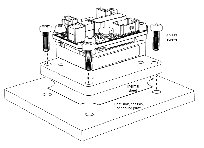
Front Installation
Front installation can be done using a Flat heatsink together with the thermal tape and 4 x M2.5 x 8 DIN965 screws.
Assemble the drive to the flat heatsink following the Back Installation process.
Use appropriate thermal interface material between the previously cleaned Flat Heatsink and the other surface.
Screw using M3 screws with appropriate torque according to the base material.