Installation
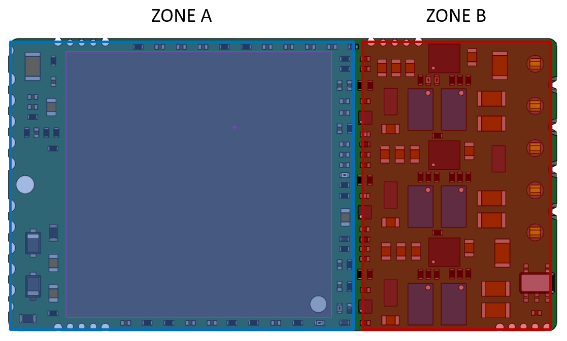
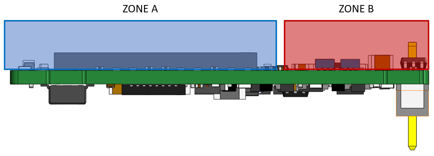
 Please do not touch the bottom of the board directly. Avoid any contact with Zone B of the board at all times of the installation and operation processes. |
|
Unboxing
When unboxing the drive please ensure the following:
- Remove it from the bag carefully avoiding any contact with Zone B.
- Check that there is no visible physical damage. If any, report it immediately to the carrier.
- Check the part number of the drive on the side label.
Installation Safety Requirements
The drive has live circuits that can be touched and entail a risk of electric shock (Protective Class 0), as well as a risk of thermal injury. It must be mounted on a closed electrical operating area to which access is restricted to skilled or instructed personnel. This enclosure, cabinet, protection, or case should have a minimum Index of Protection of IP3X. To ensure electrical safety it is also important that the environment is clean from conductive pollution or condensation when the drive is powered (Pollution degree 2).
 | WARNING HOT SURFACES! |
The drive and motor can become hot and cause severe burns. If any of the user-accessible surfaces exceeds 70 ºC, a hot-surface signal must be added. This is the responsibility of the installer. | |
 | DANGER, ELECTRIC SHOCK! |
Power and motor pins have live voltages which can exceed 50 V which can cause electric shock! Perform installation procedures without voltage. Ensure the drive is mounted on a closed electrical operating area which protects against direct contact. |
The drive may be operated without enclosure and protection against electric shock when it is supplied at Extra Low Voltage (ELV), ≤ 50 V.
Heat dissipation recommendations
Design considerations.
See Dimensions section for further details. Assembling the drive correctly is essential to:
- Provide a conduction heat dissipation path.
- It is recommended to use two soft thermal sheets - one for Zone A and one for Zone B.
- The recommended thermal pad is TG-A6200-4.pdf (tglobaltechnology.com) or a pad with similar hardness properties:
- For Zone A use the recommended thermal pad with a thickness of 1.5 mm to prevent the drive PCB from bending.
- For Zone B use the recommended thermal pad with a thickness of 2.0 mm to prevent the drive PCB from bending.
- It is not recommended to use thermal tape or sticky material for heat dissipation
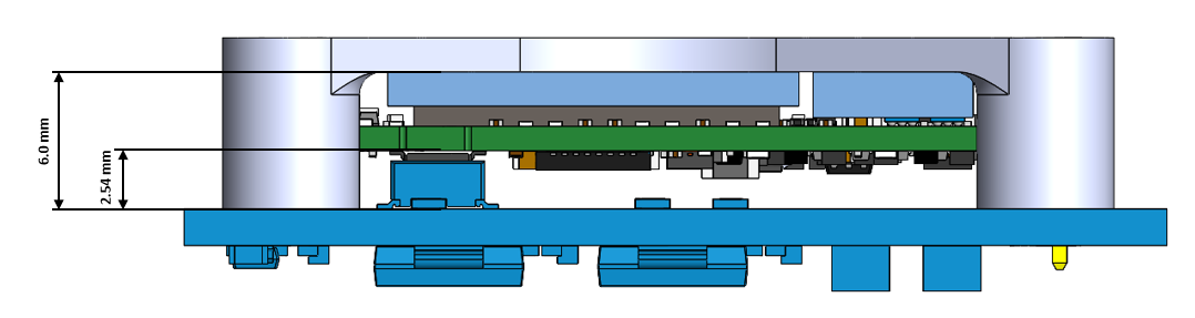
- The recommended distance between the drive and the heatsink is presented below:
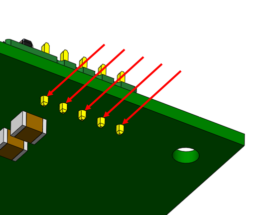
- It is recommended to solder the drive to the motherboard using the pins.
Mounting instructions
Recommended mounting instructions
- Place the thermal sheets over Zone A and Zone B. Please avoid any contact of any material other than the thermal pad with Zone B.
- Place the drive on the heatsink.
- Plug in the DEN-NET to a PCB.
- Solder the pins.
Alternative mounting instructions
In case your assembly does not allow placing the drive on the heatsink first:
- Plug in the DEN-NET to a PCB by applying pressure ONLY to Zone A, avoiding any contact with Zone B.
- Solder the pins.
- Place the thermal sheets over Zone A and Zone B. Please avoid any contact of any materials other than the thermal pad with Zone B.
- Place the heatsink on the drive.