Pinout
Connectors Overview
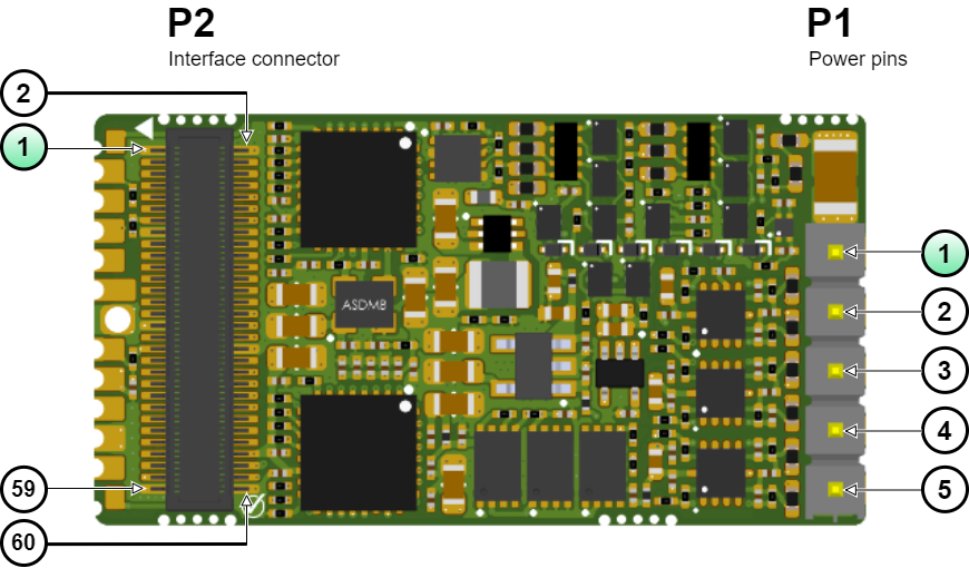
P1 Power pins
Gold plated 2.54 mm pitch pins. | ||||
# | Signal name | Type | Description | WARNING, POWER TERMINALS! |
|---|---|---|---|---|
1 | GND | Power | Power supply negative (Power Ground). Internally connected to GND_D. |   Power pins can have high voltages > 50 V, always respect clearance and creepage requirements (Typ > 0.25 mm)! Dimension PCB traces and connectors according to the current of the application! |
2 | +VBUS | Power supply positive (DC bus). | ||
3 | PHASE_A | Motor phase A for 3-phase motors, positive for DC / Voice coil motors. | ||
4 | PHASE_B | Motor phase B for 3-phase motors, negative for DC / Voice coil motors. | ||
5 | PHASE_C | Motor phase C for 3-phase motors (do not connect for DC motors). | ||
It is recommended to solder the power pins to reduce power losses. It also improves thermal performance by providing a preferential path for heat dissipation from the power stage to the environment. However, plugging and unplugging can be achieved by using a mating connector: MillMax 3305-0-15-15-47-27-10-0 socket. | ||||
P2 Interface connector
# | Signal name | Description | Type | # | Signal name | Description | Type |
|---|---|---|---|---|---|---|---|
1 | GND_D | Digital signal Ground. | Power | 2 | GND_D | Digital signal Ground. | Power |
3 | PHY1_TX_P | Port 1 Ethernet physical layer differential pairs. 50 Ω pull-up termination resistors are included on the drive. Magnetics with the center tap connected to MAGNETICS_CT (pin 54) must be added externally. If this port is not used leave these pins unconnected. | I/O | 4 | 3.3V_REF | 3.3 V ± 0.2% voltage reference output with sink/source capability up to ±10 mA. Excessive current demand or noise coupled to this pin can cause a loss of performance or even malfunction: route by following the best layout practices. | Power output |
5 | PHY1_TX_N | 6 | AN1_OUT | 0.3 V to 3 V Analog output 1. Weak output, requires buffering. | Analog output | ||
7 | PHY1_RX_P | 8 | AN1_P | Analog input 1. Can be used as a command source, brake current sensing or for torque sensing. | 16 bit differential analog input | ||
9 | PHY1_RX_N | 10 | AN1_N | ||||
11 | \ETH1_LED_LINK | Ethernet Port 1 Link signaling. Can directly drive a (typically) green LED cathode by sinking up to 3 mA while the anode is connected to 3.3 V. Place a 1k pulldown resistor to configure port 0 as capacitive coupling. Leave unconnected or pullup for magnetic coupling. If Link LEDs are desired for the axes using capacitive coupling, it is recommended to buffer the LED signal | Output | 12 | AN2_P | Analog input 2. Can be used as a command source, brake current sensing or for torque sensing. | 16 bit differential analog input |
13 | \STOA | Safe Torque Off input A (non-isolated). Both \STOA and \STOB must be high-level (3.3 V and 5 V level compatible) to allow operation of the motor. Holding different logic states (STOA ≠ STOB) for more than 1s will cause a latching fault. | Input | 14 | AN2_N | ||
15 | GND_D | Digital signal Ground. | Power | 16 | MOTOR_TEMP | Motor temperature sensor dedicated analog input. 0 to 3.3 V level high impedance input. The connection of the sensor should be done between GND_D and MOTOR_TEMP with a pull-up resistor (recommended value 1.65 kΩ) to 3.3V | 12 bit single-ended analog input |
17 | \STOB | Safe Torque Off input B (non-isolated). Both \STOA and \STOB must be high-level (3.3 V and 5 V level compatible) to allow operation of the motor. Holding different logic states (STOA ≠ STOB) for more than 1s will cause a latching fault. | Input | 18 | DNC | Reserved. Do not connect (leave floating). | - |
19 | CAN_TX | 3.3 V TTL-levels Transmit pin of CAN data frame. Requires an external transceiver to shift into CAN physical layer. | Output | 20 | DNC | Reserved. Do not connect (leave floating). | - |
21 | CAN_RX | 3.3 V TTL-levels Receive pin of CAN data frame. Requires an external transceiver to shift into CAN physical layer. If not used pull-up high. Do not leave unconnected. | Input | 22 | GPI1 | Digital Input 1. | Input |
23 | DNC | Reserved. Do not connect (leave floating). | - | 24 | GPI2 | Digital Input 2. | Input |
25 | DNC | Reserved. Do not connect (leave floating). | - | 26 | GPO1 | Digital Output 1. | Output |
27 | DNC | Reserved. Do not connect (leave floating). | - | 28 | GPO2 | Digital Output 2. | Output |
29 | DNC | Reserved. Do not connect (leave floating). | - | 30 | PWM_BRAKE | PWM output for driving a mechanical brake. Configurable up to 40 kHz. A high level indicates the motor is free to move. | Output |
31 | GND_D | Ground | Power | 32 | ABSENC1_DATA | Data input for Absolute Encoder 1 (supports SSI or up to 2 BiSS-C encoders connected in daisy chain topology). | Input |
33 | DNC | Reserved. Do not connect (leave floating). | - | 34 | ABSENC1_CLK | Clock output for Absolute Encoder 1. | Output |
35 | \BOOT | This pin can be pulled down to GND_D to force enter boot mode during power-up. Typically not necessary. If not used, always leave unconnected or pulled up with a 10 kΩ resistor. Never leave this pin permanently pulled down, as this would block the Denali boot mode. | I/O | 36 | GND_D | Digital signal Ground. | Power |
37 | DNC | Reserved. Do not connect (leave floating). | - | 38 | ABSENC2_CLK | Clock output for Absolute Encoder 2. | Output |
39 | DNC | Reserved. Do not connect (leave floating). | - | 40 | ABSENC2_DATA | Data input for Absolute Encoder 2 (supports SSI or BiSS-C encoders). | Input |
41 | DNC | Reserved. Do not connect (leave floating). | - | 42 | DIG_ENC_1A | Incremental encoder 1 A. | Input, 3.3 V level single-ended. |
43 | FAULT_SIGNAL | Fault state signaling output. Can directly drive a (typically) red LED anode at 3.3 V up to 3 mA. | Output | 44 | DIG_ENC_1B | Incremental encoder 1 B. | |
45 | ECAT_CAN_RUN | State-machine RUN green LED output for EtherCAT and CANopen. Can directly drive a green LED anode at 3.3 V up to 3 mA. | Output | 46 | DIG_ENC_1Z | Incremental encoder 1 Index. | |
47 | ECAT_CAN_ERR | State machine ERROR red LED for EtherCAT and CANopen. Can directly drive a red LED anode at 3.3 V up to 3 mA. | Output | 48 | HALL_1 | Digital hall 1. 0 to 3.3 V level high impedance input. Typical Hall sensor interface based on pull-up and schmitt trigger buffer should be provided on the interface board. | Input, 3.3 V level single-ended |
49 | \ETH0_LED_LINK | Ethernet Port 0 Link signaling. Can directly drive a (typically) green LED cathode by sinking up to 3 mA while the anode is connected to 3.3 V. Place a 1k pulldown resistor to configure port 1 as capacitive coupling. Leave unconnected or pullup for magnetic coupling. If Link LEDs are desired for the axes using capacitive coupling, it is recommended to buffer the LED signal. | Output | 50 | HALL_2 | Digital hall 2. 0 to 3.3 V level high impedance input. Typical Hall sensor interface based on pull-up and schmitt trigger buffer should be provided on the interface board. | |
51 | PHY0_TX_P | Port 0 Ethernet physical layer differential pairs. 50 Ω pull-up termination resistors are included on the drive. Magnetics with the center tap connected to MAGNETICS_CT (pin 54) must be added externally. If this port is not used leave these pins unconnected. | I/O | 52 | HALL_3 | Digital hall 3. 0 to 3.3 V level high impedance input. Typical Hall sensor interface based on pull-up and schmitt trigger buffer should be provided on the interface board. | |
53 | PHY0_TX_N | 54 | MAGNETICS_CT | Supply input for the Ethernet PHY modules, which must also supply the magnetics center tap. Two voltages can be provided:
* Must rise from 0 ms to 100 ms after 3.3V_D | Power input | ||
55 | PHY0_RX_P | 56 | 3.3V_D | 3.3 V power supply input. A well-regulated ±3%, low ripple, 1 A peak, 300 mA continuous source must be used. 3.3 V power supply should have a rise time between 30 µs and 150 µs, and should be powered up before or together with 5V. | Power input | ||
57 | PHY0_RX_N | 58 | 5V_D | 5 V logic power supply input. A well regulated ±3%, low ripple, 500 mA peak, 250 mA continuous source must be used. | Power input | ||
59 | GND_D | Digital signal Ground. | Power | 60 | GND_D | Digital signal Ground. | Power |
Notes and naming conventions:
All pins are tolerant to 3.3 V unless otherwise noted.
Unused digital outputs should be left unconnected.
Unused digital inputs should be connected to GND_D.
Unused analog inputs should be connected to 1.65V ± 3% by means of a voltage divider from 3.3V_REF. Minimum resistors should be ≥470 Ω (≥4.7 kΩ recommended).
"_P" and "_N" indicate positive and negative terminals of differential signals
"\" Indicates inverted (active low) signal
"NC" means Not Connected. Pins marked with NC can be tied to GND or 3.3 V, but the best practice is to leave them unconnected.
"DNC" means Do Not Connect. Pins marked with DNC must not be tied to any driving voltage, including GND or 3.3 V.
Manufacturer | Denali NET connector | Required mating connector | Description |
|---|---|---|---|
Molex | 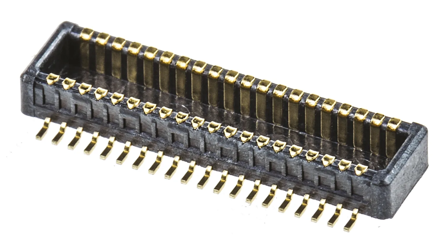 | 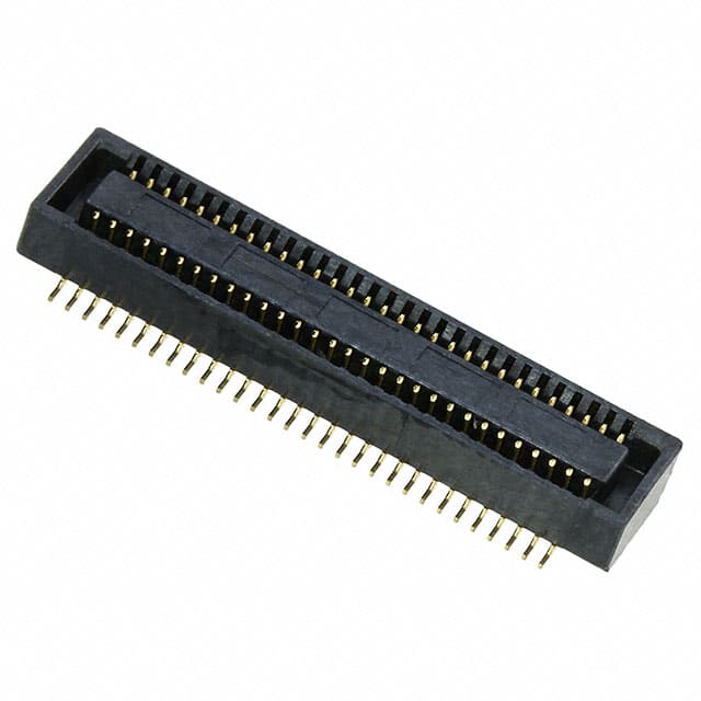 | 60-pin stacking board connector. 0.5 mm pitch. Center strip, gold-plated surface mount contacts. 2.5 mm stacking height. Molex SlimStack connectors operation and storage temperature, when mounted, is -45 ºC to 105 ºC. |