Safety Manual for DEN-NET
Revision History
Rev. | Date | Description |
|---|---|---|
A |
| First release of the document. |
B |
| Formatting updated. Multiple content updates:
|
C |
| PFH and MTTFd values updated |
D |
| Logic Supply Connection and Logic Supply Protection Example added. Example of multi-axis connection provided. |
E |
| Application Examples removed |
F |
| Some minor modifications:
|
G |
| Minor corrections after revision.
|
H |
| Minor corrections after revision: PFH value updated |
Scope
This document defines the DEN-NET Safety Specifications and the Integration Requirements that must be fulfilled in the user interface board to guarantee Functional Safety.
Safety Concept
The DEN-NET is a product of the Novanta Summit Safety Series, a family of servo drives with Functional Safety capabilities. The product consists on a Summit Servo Drive with a hardware-implemented STO function.
The Safe Torque Off (STO) is a safety function that prevents motor torque in an emergency event while DEN-NET remains connected to the power supply. When STO is activated, the power stage is disabled by hardware and the drive power transistors are disconnected, no matter what control or firmware does. The motor shaft will slow down until it stops under inertia and frictional forces. Although not common, in the event of a failure of the power stage during an STO situation, the maximum expected motor movement with torque can be up to 180º electrical degrees. The system must be designed to avoid any hazard in this situation. STO safety function is only considered when the drive is controlling three-phase permanent magnet synchronous rotating motors. STO does not apply to DC brushed motors.
If the STO inputs are not energized, the transistors of the power stage are turned off and an STO fault is notified. In order to activate the power stage, and therefore allow the motor operation, the two STO inputs must be energized (high level). STO inputs should not be confused with a digital input configured as enable input, because enable input is firmware controlled and does not guarantee intrinsic safety as it can be reconfigured by a user.
In order to ensure redundancy and safety, the DEN-NET includes 2 separate STO inputs that must be activated or deactivated simultaneously. A difference of state between \STO_A and \STO_B inputs will be interpreted as an abnormal situation and trigger a fault. After some time, the abnormal fault will become latching and require a power supply reset.
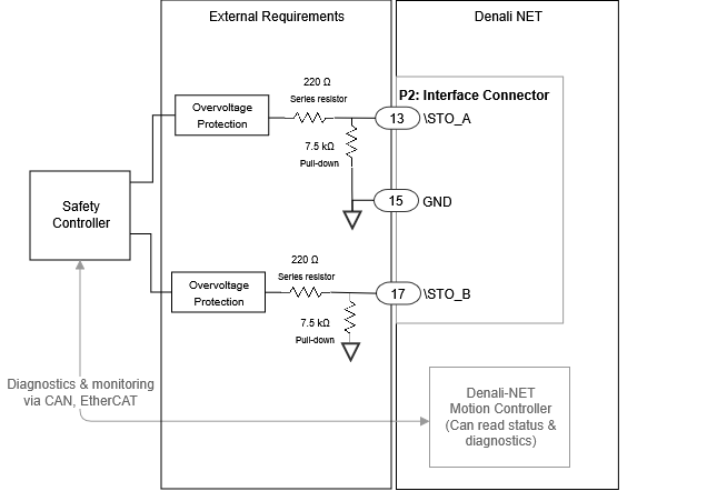
Since DEN-NET is a pluggable module intended for being integrated on an electronic interface board, it requires some external electronic components to fulfill the safety requirements:
External overvoltage protection (or equivalent) is required to limit STO input voltage.
Input series resistor to limit current and avoid system destruction in case of internal fault.
Input pull-down resistor to guarantee low-level. Otherwise, safety function fault tolerance and reaction times, won't be fulfilled.
Safety Specifications
Safety Function | Safety relevant parameters according to EN 61508:2010 (certification pending) | Safety relevant parameters according to EN ISO 13849-1:2015 (certification pending) | Safety Function Reaction Time |
|---|---|---|---|
Safe Torque Off (STO) The function prevents rotating torque from being provided to the motor. | Safety integrity level: SIL3 PFH: ≤ 4.6 e-12 1/h SFF: ≥ 99 % (High) | Performance Level: PLe Category: 3 MTTFd ≥ 100 years (High) DCavg: 99% High | tSF ≤ 9.5 ms The Safety Function Reaction time is measured as the time since one of the STO inputs (STO_A or STO_B) goes below VIL and the STO function actuates (power transistors deactivated). |
Safety Specification | Value |
|---|---|
Command Source | Safe Inputs |
Standards compliance | Targeted standards:
|
Fault Reaction Time | ≤ 12 ms System maximum Reaction Time in case of a Detected Fault or safety function activation. |
High-demand mode | The EUC (Equipment Under Control) is considered as a high-demand or continuous demand mode system. |
Mission Time | The mission time of the EUC is of 20 years. |
Diagnostic Time Interval | In order to guarantee the correct operation of the safety functions, the user must execute the External Diagnostic Test (see further information below) regularly. The diagnostic test interval is defined as a minimum of 1 activation per 3 months. |
Included Diagnostics |
Status of \STO_A, \STO_B, ABNORMAL_FAULT, and SUPPLY_FAULT can be read from the communications. STO firmware notificationA STO stop is notified to the motion controller and creates a fault that can be read externally from any communication interface, however, STO operation is totally independent and decoupled from control or firmware. |
External Diagnostic Test
The operation of the STO diagnostic circuits must be verified at least once per 3 months. The following procedure details a method to verify the STO diagnostic circuits and the external wiring. If the procedure results are not the expected ones, safety could be violated and the system cannot be used. Note that it is responsibility of the customer to prevent any hazards related to motor movement during this proof test.
The procedure requires the drive to be connected to a three-phase permanent magnet synchronous rotating motor.
Procedure Step | Action |
|---|---|
1 | Power on the drive. |
2 | Deactivate the Safety Function by providing:
|
3 | Transition to a normal operation state where the power stage can be enabled, and perform some motor movement. |
4 | While the motor is enabled, activate the Safety Function by providing:
|
5 | Remain in this state more than tABN_LATCH_MAX seconds. |
6 | Deactivate the Safety Function by providing:
|
7 | Remain in this state more than tABN_LATCH_MAX seconds. |
8 | Without performing a power reset, verify that the power stage can be enabled again, and perform some motor movement. From Motionlab 3 software or communication channel, check that no Abnormal Fault appears. |
Interface and Integration Requirements
The following table details the Interface and Integration Requirements that guarantee Functional Safety.
Integration Requirement | Value | |
|---|---|---|
STO Inputs Interface electrical characteristics | Input pins | \STO_A and \STO_B |
Number of independent channels | 2 | |
Type of Inputs | Active-low. Digital inputs with ESD protection. | |
STO Inputs Mandatory External Circuit |
See “External Requirements for STO inputs and Logic Supply“ below. All following calculations are considering the use of the STO Input Mandatory External Circuit | |
Maximum input LOW level (VIL) | 0.8 V (below this value the \STO is ACTIVE). STO input voltage is measured before the Mandatory External Circuit. See “External Requirements for STO inputs and Logic Supply“ below. | |
Input current at VIL voltage (IIL) | > 50 µA | |
Minimum Input HIGH level (VIH) | 3.1 V (above this value the \STO is INACTIVE). STO input voltage is measured before the Mandatory External Circuit. See “External Requirements for STO inputs and Logic Supply“ below. | |
Input current at VIH voltage (IIH) | < 420 µA | |
Maximum absolute ratings |
STO input voltage is measured before the Mandatory External Circuit. See “External Requirements for STO inputs and Logic Supply“ below. Note: The system is single fault tolerant. No additional faults (internal or external) can be handled after the external failure. | |
Maximum Input current |
| |
ESD capability | EN 61000-4-2 (ESD) ± 15 kV (air), ± 8 kV (contact) | |
STO Inputs Interface timing characteristics | STO reaction time (activation time) | tSF ≤ 9.5 ms The Safety Function Reaction time is measured as the time since one of the STO inputs (STO_A or STO_B) goes below VIL and the STO function actuates (power transistors deactivated). |
STO deactivation time | tSTO_DEACT ≤ 7 ms The STO Deactivation time is measured as the time needed for deactivating the HW STO with push-pull driver with valid VIH. | |
Max. activation pulse filtering (OSSD) | tpulse ≤ 400 µs Pulse filtering considers activation VIH > 4.5 V and deactivation by means of open circuit (discharge through STO Inputs Mandatory External Circuit) See “Pulse Filtering Circuit for OSSD” section below | |
Max. activation pulse filtering (OSSD) with OSSD external capacitor | The use of an additional capacitor COSSD in parallel to the pull-down resistor increases the activation pulse filtering for OSSD:
Pulse filtering considers activation VIH > 4.5 V and deactivation by means of open circuit (discharge through STO Inputs Mandatory External Circuit) See “Pulse Filtering Circuit for OSSD” section below | |
STO reaction time (activation time) with OSSD external capacitor | The use of an additional capacitor COSSD in parallel to the pull-down resistor increases the STO reaction time:
The Safety Function Reaction time is measured as the time since one of the STO inputs (STO_A or STO_B) goes below VIL and the STO function actuates (power transistors deactivated). | |
Abnormal STO diagnostic time | tABN ≤ 9.5 ms Minimum STO signals discrepancy time that causes an Abnormal Fault and activates the Safety Function. | |
Max. abnormal STO latching time | tABN_LATCH_MAX ≤ 2.5 s Minimum STO signals discrepancy time that guarantees a latching Abnormal STO Fault. | |
Min. abnormal STO latching time | tABN_LATCH_MIN ≥ 0.6 s Maximum STO signals discrepancy time that guarantees that Abnormal STO Fault is not latched. | |
Logic Supply Voltage Range |
Safety function is maintained with an overvoltage failure within the specified range, but the other system functions could become non-operational. | |
Logic Supply Connection |
In the event of a failure in the power stage, any logic interface could become connected to Power Supply. The safety function would be maintained, but any logic interface pin could become connected to a dangerous voltage. If not properly decoupled, this could risk the safety integrity in other drives or elements in the system. For this reason, it is not recommended that the safety-related inputs (STO Inputs and Logic Supply) share connection with other pins (even from the same drive) without protection elements in between. See “External Requirements for STO inputs and Logic Supply“ section below. | |
Power Supply Voltage Range | 48 V SELV (range from 8 V to 60 V; maximum failure voltage 60 V) Note: The system is single fault tolerant. No additional faults (internal or external) can be handled after an external failure. | |
Thermal Interface | The System requires to be properly assembled to a case or heatsink with a thermal material in between. See Product Manual Installation chapter for further details. | |
External Requirements for STO inputs and Logic Supply
The following conceptual diagram summarizes the external requirements for the STO inputs and Logic Supply
Pulse Filtering Circuit for OSSD
The following diagram summarizes how to implement the Pulse Filtering circuit for OSSD inputs.
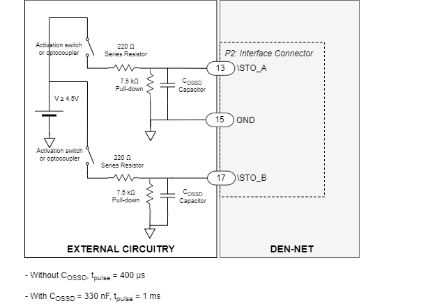
The following diagram depicts the \STO_x signals when using pulse filtering for OSSD.

STO Operation States
The truth table of the STO inputs is shown next indicating the different states of the system:
Mode | State | \STO_A status / level | \STO_B status / level | Power stage status | STO report bit status | STO abnormal fault | State description | ||
|---|---|---|---|---|---|---|---|---|---|
Normal operation | STO Enabled | 0 | < VIL | 0 | < VIL | OFF | 0 | 0 | The system logic is powered, but the STO function is activated. Therefore, no torque can be applied to the motor. STO trip is reported to the MCU and to the safety circuitry. This is intended safe torque off with dual-channel operation. |
Torque enabled (STO inactive) | 1 | > VIH | 1 | > VIH | Can be enabled | 1 | 0 | The STO function is deactivated, and torque can be provided to the motor. The motor can run under firmware control. This is the normal operation state. | |
Abnormal operation | Abnormal STO | 0 | < VIL | 1 | > VIH | OFF | 0 | 1 | If any issue is detected on the dual-channel STO function (the channels logic level is different), an Abnormal Fault is detected, activating the Safety function and reporting it via FW. This state avoids the application of torque to the motor. |
1 | > VIH | 0 | < VIL | OFF | 0 | 1 | |||
Abnormal STO Latched | x | - | x | - | OFF | NOR (\STO_A, \STO_B) | 1 | If the Abnormal Fault persists for ≥ tABN_LATCH_MAX, the fault becomes latching, maintaining the Safety Function activated until a power supply reset cycle. | |
Abnormal Supply | x | x | x | x | OFF | x | x | If a voltage out of the limits is detected on the internal logic voltages, the system is conducted to a safe state, similar to power-off. Only if the safe logic voltages are recovered (usually after reparation or restart), the system can return to any other state. | |
\STO_A and \STO_B signals should always change at the same time with a maximum of tABN mismatch. This is necessary to have 2 channel redundancy and allow diagnostics, as a mismatch will cause an abnormal fault.
The logic level of an STO signal between VIL and VIH is unknown. If supplied at unknown level, \STO_A and \STO_B could have different logic values and trigger an abnormal latching fault.
In order to ensure this, do not add big capacitors (> 1 µF) in parallel to the STO inputs as this may cause faults during activation or deactivation of the STO.
Les signaux \STO_A et \STO_B doivent toujours changer en même temps avec un décalage maximum de tABN. Ceci est nécessaire pour avoir une redondance à 2 canaux et permettre le diagnostic, car une discordance provoquera une anomalie de fonctionnement.
Afin de garantir cela, n'ajoutez pas de gros condensateurs (> 1 µF) en parallèle aux entrées STO, car cela pourrait provoquer des défauts lors de l'activation ou de la désactivation du STO.
Le niveau logique d'un signal STO entre VIL et VIH est inconnu. S'ils sont alimentés à un niveau inconnu, \STO_A et \STO_B peuvent avoir des valeurs logiques différentes et provoquer une anomalie de fonctionnement.
Application and Environmental Conditions
Functional Safety can only be guaranteed in the following environmental conditions:
Motor Type | Functional Safety is only considered when the drive is controlling three-phase permanent magnet synchronous rotating motors. STO does not apply to DC brush motors. | |
|---|---|---|
Uncontrolled Motor Movement |
In the event of a failure in the power stage, the motor shaft may rotate up to 180º electrical degrees. It is the responsibility of the customer to prevent any hazards related to this unexpected motor movement. | |
Environmental Conditions1 | Pollution degree | Pollution degree 2 with an IP54 enclosure installation. |
Over-voltage category | II | |
Altitude | < 2000 m above sea level. | |
Ambient Temperature (Operating) | -20 ºC to 60 ºC | |
Case Temperature (Operating) | -20 ºC to 70 ºC The System requires to be properly assembled to a case or heatsink with a thermal material in between. See Product Manual Installation chapter for further details. | |
Storage Temperature (Non-Operating) | -40 ºC to 100 ºC | |
Vibration | 10 Hz to 150 Hz, 1 g. Test according to EN 60068-2-6:2008 - Test Fc: Vibration (sinusoidal) | |
Shock | ±5g Half-sine 30 msec Test according to EN 60068-2-27:2009 - Test Ea and guidance: Shock | |
EMC | Functional Safety has been tested according to EN IEC 61800-3:2018 procedures with the extended ranges of EN 61800-5-2:2017. The interface board must meet the same EMC standards (EN IEC 61800-3:2018 with extended ranges of EN 61800-5-2:2017). To fulfill the EMC requirements the use of the following elements is required:
| |
Environmental | The interface board must meet the following environmental standards:
| |
1: The drive can operate outside this range as indicated in the Product Description, however, it will not meet Functional Safety requirements.