Velocity modes (CSV, PV, V)
This mode is used to command the velocity of the actuator. It requires a proper configuration of the commutation sensor.
The commutation sensor configuration process is described in the Commutation section.
If software position limits are enabled using this mode of operation, the drive will generate a fault if the position limits are exceed. Set them to 0 to disable this functionality.
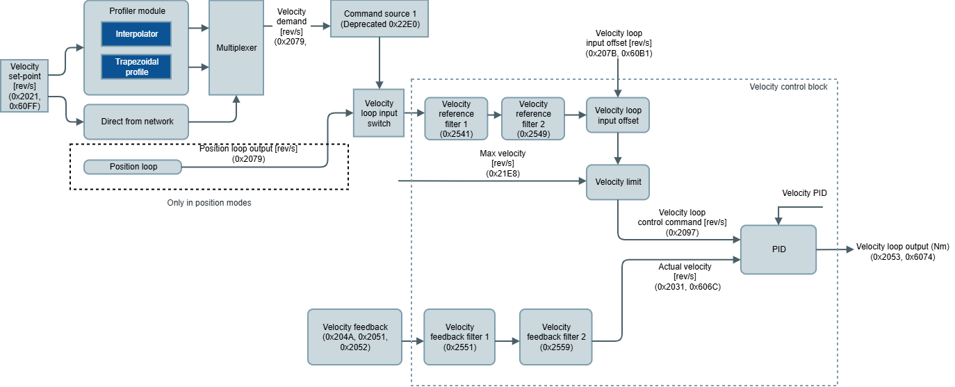
The velocity limit block is available to protect the system in front of high commanded velocities unsupported by the system. Max. velocity determines this limit and is applied to the velocity demand. The result of applying this limit is visible through velocity loop control command.
This mode can be sourced directly from the network or through the profiler mode. This last one allows two configurations: using interpolator (CSV) or trapezoidal profile (PV).
The velocity feedback block delivers the actual velocity of the system based on the velocity feedback sensor.
The drive supports multiple feedback options. Take a look at the Feedbacks section.
The implemented PID module follows the next block diagram:
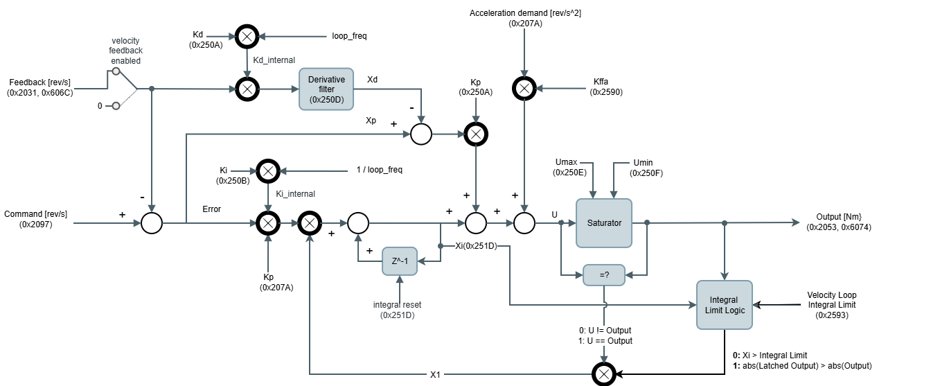
The output of the control loop at the kth sample is:
Where:
U is the output before entering in the saturator, it is torque in [Nm].
The output after saturator is limited to the values Umax and Umin, so if the U signal is outside these parameters, the output is clamped.Command c is the Command signal (Output of the Reference + Filters + offset), in mechanical revolutions per second [rev/s].
Feedback f is the Filtered Feedback signal (Output of the Feedback + Filters), in mechanical revolutions per second [rev/s].
Kp, Ki and Kd are the PID gains. Kp in [Nm/(rev/s)], Ki in [Hz] and Kd in [s2].
Kffa is the feed-forward acceleration gain, in [Nm/(rev/s2)].
ademand is the acceleration demand, in [rev/s2].
xp is the proportional path:
xi is the integral path:
where x1 is:
The integral accumulator value can be reset at any time externally.xd is the derivative path:
Derivative incorporates also a derivative IIR filter, where c1 and c2 are the derivative filter coefficients:T is the control loop period, in [s], and
, in [s], is the reciprocal of the desired filter bandwidth
The output of the velocity controller is connected to the torque command (before the filters and offset) of the torque control.
All velocity modes work with a PID controller and the related registers are:
0x2590 - Velocity loop Kffa (Kffa)
0x251D - Velocity loop integral value is the integral accumulator value (xi).
0x251B - Velocity loop integral reset allows to reset the integral part (integral reset).
0x2079 - Velocity demand is the reference input of the PID. It's an output of the profiler.
0x207A - Acceleration demand is an output of the profiler.
0x2097 - Velocity loop control command is the command value after the filter, offset and limits are applied (Command signal from the diagram).
0x21E3 - Velocity control loop error is the difference between the reference and feedback values in the control loop.
0x2031 - Actual velocity, 0x606C - Velocity actual value is the feedback input after the filter is applied (Filtered Feedback signal from the diagram).
0x2021 - Velocity set-point, 0x60FF - Target Velocity is the target commanded to velocity modes.
On the other hand, the implemented controller supports additional features:
Velocity feedback enabled allows opening the loop of the PID. It is configured with register 0x2510 - Control loops feedback options. The feedback path is removed from the real feedback signal and it forces a value of 0.
0x2520 - Position & velocity loop rate contains the update rate of execution of the PID.
0x2518 - Velocity loop status contains information about PID functionality;
Loop enabled. This flag activates if the current loop is enabled and in use.
Upper saturator active (momentary). This flag activates when the current loop is saturating on the upper limit. The flag deactivates when the upper saturation is not happening anymore.
Lower saturator active. This flag activates when the current loop is saturating on the lower limit. The flag deactivates when the lower saturation is not happening anymore.
Command limit. This flag activates when the velocity loop control command signal is above the max. velocity limit. The flag deactivates when the velocity loop control command signal is below the max. velocity threshold.
Set-point limit. This flag activates when the velocity set-point is above the max. velocity limit. Under this situation, the velocity demand is limited to max. velocity. The flag deactivates when the velocity set-point is below max. velocity threshold.
0x2522 - Control loops option code allows to enable or disable the continuity of the PID output. If enabled, it would prevent instantaneous undesired PID outputs. Also, changing the PID constants can cause discontinuities in the control output.
If continuity is going to be used, it is recommended to have a non-zero integral constant.
Do not use this feature while tuning the system since it could be misleading.
0x21F3 - Velocity window and 0x21F4 - Velocity window time are used to determine when the actual velocity has reached the velocity set-point. Depending on the selected feedback, the system environment, and the drive configuration, the velocity ripple amplitude changes. These configurable parameters are used to determine what is the maximum tolerable error between the two mentioned parameters.
0x21DC - Velocity following error window and 0x21DD - Velocity following error timeout are used to determine when the actual velocity is not following the velocity demand as expected, it means the error between them is too big. The response of the system if the following error is detected is configurable by the 0x261D - Velocity following error option code.
Integral limit and anti-windup protection logic uses the information from the accumulated value (Xi) in the integral path and the actual PID output (Output [Nm]) to enable/disable the integral path:
When the accumulator of the integral path overcomes the value defined in the 0x2593 - Velocity loop integral limit:
The integral path is disabled (X1 = 0)
The integral accumulator value is set to the integral limit
The output of the PID is stored in a variable
For restoring the integral path (X1 = 1), the next conditions are required:
If the new value PID output is smaller than the stored one, the integral path is restored.
0x2593 - Velocity loop integral limit - sets the value for comparison of the integral term (Xi)
0x251D - Velocity loop integral value - indicates the value of integral term (Xi)
0x251B - Velocity loop integral reset - resets the integral value of the velocity control loop
It is not recommended to use this feature together with the control loop option “continuity” and live-changing the PID parameters. The continuity feature of the control loops recalculate the integral accumulator to keep the value of the output. Therefore, under some scenarios, the new integral accumulator is higher than the limit and the continuity feature might not work as expected.
Filters and offset
Additionally to the PID controller, two biquad filters in cascade are available for both PID input sources: Reference and feedback. The purpose of these filters differs on every application, but basically they help to improve feedback readings or compensate undesired system dynamics. There are multiple configurations for every filter:
Low pass filter
High pass filter
Band pass filter
Peak filter
Notch filter
Low shelf filter
High shelf filter
The next parameters configure every filter type:
Filter type | Frequency | Q-factor | Gain (dB) |
|---|---|---|---|
Low pass | X | X | - |
High pass | X | X | - |
Band pass | X | X | - |
Peak | X | X | X |
Notch | X | X | - |
Low shelf | X | - | X |
High shelf | X | - | X |
The related parameters for filter configuration are:
0x2560 - Velocity reference filter 1 type & 0x2568 - Velocity reference filter 2 type
0x2561 - Velocity reference filter 1 frequency & 0x2569 - Velocity reference filter 2 frequency
0x2562 - Velocity reference filter 1 Q-factor & 0x256A - Velocity reference filter 2 Q-factor
0x2563 - Velocity reference filter 1 gain & 0x256B - Velocity reference filter 2 gain
0x2550 - Velocity feedback filter 1 type & 0x2558 - Velocity feedback filter 2 type
0x2551 - Velocity feedback filter 1 frequency & 0x2559 - Velocity feedback filter 2 frequency
0x2552 - Velocity feedback filter 1 Q-factor & 0x255A - Velocity feedback filter 2 Q-factor
0x2553 - Velocity feedback filter 1 gain & 0x255B - Velocity feedback filter 2 gain
In some applications, the PID and the filters are not enough for proper control. In these cases, there is an additional input through the reference signal to the PID (after filters are applied) that is identified as Offset in the PID diagram. The purpose of this 0x207B - Velocity loop input offset is to be used by an external main device/instance to compensate for the system dynamics based on information that cannot be read directly by the drive.
Closing position loop on the main device/instance
In some applications, the drive is configured to work in velocity mode with a "simple" controller diagram whereas the position loop is implemented by an external main device/instance or sometimes two different feedbacks are used to measure the same parameter to add redundancy in the feedback channel. For those applications where additional feedback is required to be monitored outside the drive, an auxiliary feedback sensor is available to map extra feedback to the drive. The readings are available on auxiliary feedback value in raw format (cnt). Any mappable feedback used for position and velocity can be used as an auxiliary feedback sensor.
Example
A system uses a high-resolution digital incremental encoder and digital halls for work in velocity mode in a multi-turn based system. An additional external SSI encoder wants to be used by the main device/instance of the application to command different profiles based on the position, but this main device/instance does not have the required electronics to read the SSI. The drive can be configured as a bridge mapping the SSI into the auxiliary feedback sensor. Then it processes and returns the SSI position information directly through the network channel.
Velocity mode (V)
Velocity (V) mode uses the above control scheme, connecting the velocity set-point input from the application directly to the Velocity demand signal mentioned above.
Note
Set-points will begin being taken into account after transitioning to the "operation enabled" state on the drive.
Cyclic Synchronous Velocity (CSV)
Cyclic Synchronous Velocity mode (CSV) uses the above control scheme as well but connects the velocity demand to the linear profile of the set-point manager.
Note
The profile will start generating points depending on the selected 0x21C8 - Profiler latching mode. If latching is disabled, the linear profile starts immediately upon a change of velocity set-point. If latching is enabled, the linear profile starts after a change of velocity set-point and its confirmation through lathing bit from the control word.
Warning
It is mandatory to configure the interpolation time mantissa and interpolation time exponent. The value of these parameters will determine how the linear profile will be performed. The product of these two parameters should match the time that will take to update the current quadrature set-point. More information about the linear profile can be found in the Set-point manager and interpolator buffer section.
Profile velocity (PV)
Profile velocity (PV) uses the same control scheme as CSV. The difference is that the selected profiler of the set-point manager is trapezoidal instead of linear. This profile requires additional user-configurable parameters. These are
Note
The profile will generate new points that will begin depending on the selected profiler latching mode. If latching is disabled, the linear profile starts immediately upon a change of velocity set-point. If latching is enabled, the linear profile starts after a change of velocity set-point and its confirmation through latching bit from the control word.
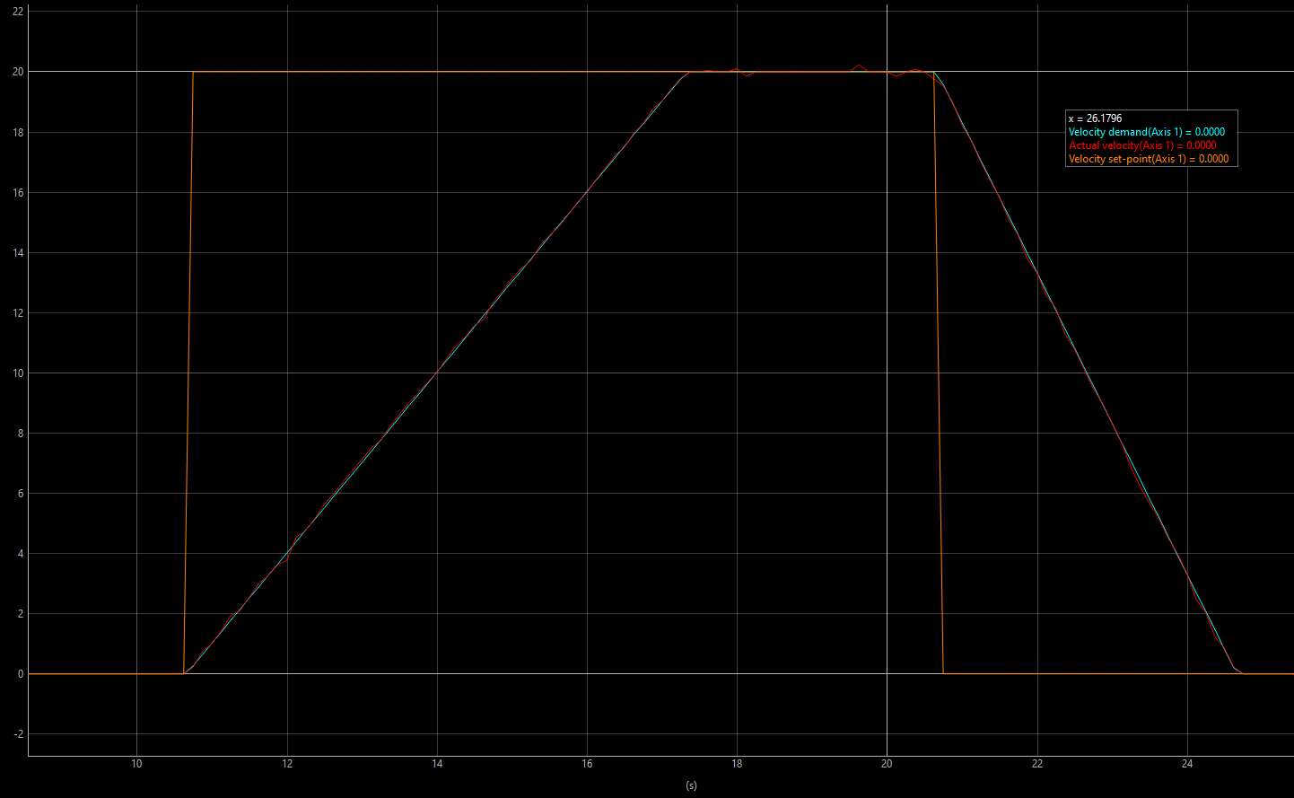
The trapezoidal profile is composed of two stages in velocity mode: First, a linear acceleration/deceleration stage followed, and secondly, a constant velocity stage when either the velocity set-point, the profiler max. velocity or the max. velocity limit is reached.
In this mode, the profile is not time-restricted.
Example
In the following picture, a trapezoidal velocity trajectory can be observed (composed of two set-point commands: 20 rev/s and 0 rev/s). Note that the acceleration and deceleration are different.