Safety Manual for DEN-S-NET Safe Motion
Revision History
Rev. | Date | Description | ||
|---|---|---|---|---|
A | First release of the DEN-S-NET Integration Requirements | |||
B | Preliminary Public Release of Integration Requirements for DEN-S-NET | |||
C | Safety Concept and Specifications Added | |||
D | Comments corrected. | |||
E | Final Safety values updated. Some Integration Requirements added. Pinout section removed (already included in the product manual) | |||
F | Safe Firmware version added. Heatsink Requirement removed. | |||
G | Mentioned that only TwinCAT from Beckhoff can be used for configuration | |||
H |
| Updated safety manual with comments from application, new safety integrity value, due to changes in safety calculation, new safe firmware version. | ||
J |
| Writing style and clarification improvements Section Safety Concept | ||
K | Safe homing infobox is changed. Statement that SI cannot be used has been removed |
Scope
This document defines the DEN-S-NET Safety Specifications and the Integration Requirements that must be fulfilled in the user interface board to guarantee Functional Safety.
Contact Information
Novanta Technologies Spain S.L.
C/ Avila 124, 2-B
08018 Barcelona
Spain
Telephone: +34 932 917 682
E-mail: hello@ingeniamc.com
Web site: drives.novantamotion.com
Safety Concept
The Novanta Summit Safety Series is a family servo drives with Functional Safety capabilities. The series is based on a monitoring board (Safety Core) plugged into a Novanta Summit Servo Drive with hardware implemented STO function.
The Safety Core receives safety function commands via FSoE network communication (ETG 6100), a safety communications protocol based on the black-channel concept, or via safe digital inputs. Additionally, the Safety Core reads in motion feedback by encoders mounted on the motor and load shaft and compare them. In the case of receiving the command, overpassing the motion limits provided by feedback or detecting a system fault, the system enters a safe state, which includes activation of STO. The control of the power stage will remain on the Novanta Summit Servo Drive, whose software is considered non safety-related.
To guarantee safety integrity, the Safety Core is designed with two redundant channels, based on two MCUs that read the safety commands and monitor equal system operation. Each MCU activates an individual STO channel, which is also redundant.
Communication via FSoE
FSoE operates over the EtherCAT network using a “black channel” approach. This means the underlying communication medium is not safety-certified, but the safety of the data is ensured by the FSoE protocol itself.
Since DEN-S-NET is a pluggable module intended for being integrated on an electronic interface board, it requires some external electronic components to fulfill the safety requirements (see Integration Requirements).
Safe Torque Off (STO) Function
The Safe Torque Off (STO) is a safety function designed to immediately prevent motor torque in emergency or fault situations, without disconnecting the system from power.
When STO is activated, the power stage of the drive is disabled by hardware.
This means the drive’s power transistors are physically disconnected, regardless of any control commands or firmware status.
As a result, the motor shaft slows down and stops naturally, due to inertia and friction—not active braking.
STO can be triggered in three ways:
Via FSoE communication
Via Safe Input signals
Automatically by a safety monitoring function, if STO is configured as the error reaction for that function.
In the event of a failure of the power stage during an STO situation, the maximum expected motor movement with torque can be up to 180º electrical degrees. The end user of the safe product must design the system in order to avoid any hazard in this situation. STO safety function is eligible only when the drive is controlling three-phase permanent magnet synchronous rotating motors.
The safety functions are not applicable for DC brushed motors.
When powering off the drive, STO is enabled by default, and this feature is not configurable.
Applicability
STO is only valid when the drive is controlling three-phase permanent magnet synchronous rotating motors.
STO, along with SS1-t and SI, is not applicable for DC brushed motors.
Safe Input (SI) Function
The Safe Input (SI) is designed to read a redundant safety input signal, which consists of two physical input channels. Its behavior is defined as follows:
If both channels are high, the SI is interpreted as high-level.
If only one channel is low, the SI is interpreted as low-level.
If the two channels differ (i.e., one is high and the other is low) for a short period, this is considered an Abnormal Fault, typically caused by a wiring issue or signal inconsistency.
If this fault condition persists for an extended period, it becomes a latching fault. Once latched, the fault cannot be cleared automatically and requires a power cycle to reset the system.
The SI value is transmitted via FSoE, ensuring safe communication over the EtherCAT network.
The activation of SI can trigger the activation of a configurable safety function (e.g., STO, SS1‑t, SS1‑r, SS2-t or SS2-r).
Safe Homing (SH)
The Safe Homing (SH) configuration is responsible for marking the zero position of the axis connected to the safe drive.
To perform the safe homing, you require a safe input extracted from the FSoE Master.
The Safe Homing must be performed before SP and SLP.
Safe Position (SP)
The Safe Position (SP) is a Safe Process Data over FSoE that is essential for supporting safety features. Due to feedback redundancy, the drive is able to report a reliable position extracted from the internal calculations of the safety core.
The Safe Homing must be performed before SP.
Safe Velocity (SV)
The Safe Velocity (SV) is a Safe Process Data over FSoE that is essential for supporting safety features. Due to feedback redundancy, the drive is able to report a reliable velocity extracted from the internal calculations of the safety core.
Safe Stop 1 (SS1)
The Safe Stop 1 (SS1) (safely configured via FSoE or through Safe Input signals) initiates a motor deceleration and performs the STO function afterwards. The trigger of STO function can be configured as follows: performs the STO function depending on the established configuration (safely configured via FSoE or through Safe Input signals). These are the two ways how the STO is able to be reached:
SS1-t: By the initialization of the SS1, the motor decelerates and after a specified SS1 Time to STO, the STO is performed. This configuration can be referenced as the time controlled SS1.
SS1-r: By the initialization of the SS1, the motor decelerates and this deceleration rate is being monitored to be within the selected limits to stop the motor. When motor speed is below a specified limit, the STO function is performed. This configuration can be referenced as the ramp/deceleration controlled SS1.
The deceleration rate of the motor is configured in the non-safe part of the drive. The deceleration limit is defined in the safe part of the drive.
Safe Stop 2 (SS2)
The Safe Stop 2 (SS2) (safely configured via FSoE or through Safe Input signals) performs a deceleration and afterwards an SOS. These are the two ways how the SOS is able to be reached:
SS2-t: By the initialization of the SS2, the motor decelerates and after a specified SS2 Time to SOS, the SOS is performed. This configuration can be referenced as the time controlled SS2.
SS2-r: By the initialization of the SS2, the motor decelerates and this deceleration rate is being monitored to be within the selected limits to stop the motor. When motor speed is below a specified limit, the SOS function is performed. This configuration can be referenced as the ramp/deceleration controlled SS2.
Safe Operating Stop (SOS)
The SOS (Safe Operating Stop) function maintains the machine in a safely stopped condition without removing power to the motor. This allows the drive to continue controlling and holding the position securely.
SOS ensures that the motor remains stationary by actively monitoring that no unintended motion occurs.
Unlike STO, power to the motor is not removed, enabling torque to hold the current position.
SOS can be triggered via FSoE communication or Safe Input signals.
Safe Speed Range (SSR)
The SSR (Safe Speed Range) function continuously verifies that the machine operates within a defined safe minimum and maximum absolute speed range. SSR can be configured with up to 8 instances.
Bidirectional Speed Limits: Ensures actual speed always stays between a lower and upper safe boundary.
Fault Response: If speed exceeds the allowed range, the function triggers a configured safe reaction (e.g., SS1‑t, SS1‑r, or STO).
Configuration: Safe limits are set via FSoE.
Safely-Limited Speed (SLS)
The SLS (Safely-Limited Speed) function supervises that the machine’s speed does not exceed a defined absolute maximum safe limit. SLS can be configured with up to 8 instances.
Upper Threshold Monitoring: The drive continuously checks that actual speed stays below the permitted safe threshold.
Symmetrical Limit: The speed limit applies equally in both rotational directions.
Fault Handling: Exceeding the limit triggers a a configured safe reaction (e.g., SS1‑t, SS1‑r, or STO).
The configured safe state will be transitioned only once the safe function is activated. If the boundaries were crossed while the SLS is inactive, no reaction will be performed.
Safely-Limited Position (SLP)
The SLP (Safely-Limited Position) function keeps machine movement within predefined safe absolute position boundaries (either in positive or negative direction, having that the upper limit > lower limit). SLP can be configured with up to 8 instances.
Position Window Monitoring: Ensures the motor/axis does not leave a specified safe zone.
Hazard Prevention: Prevents the system from entering dangerous areas or exceeding mechanical limits.
Reaction: Violations of safe boundaries cause a transition to a defined safe state (e.g., SS1‑t, SS1‑r, SS2-t, SS2-r or STO).
The configured safe state will be transitioned only once the safe function is activated. If the boundaries were crossed while the SLP is inactive, no reaction will be performed.
The Safe Homing must be performed before SLP.
Safely-Limited Increment (SLI)
The SLI (Safely-Limited Increment) function supervises incremental motion steps (respect the position when the function was activated) to ensure each movement stays within safe distance limits.
Step-Size Monitoring: Every commanded or measured movement is evaluated against a maximum upper and lower allowed increment.
Overshoot Detection: Any movement exceeding the configured increment triggers a configurable safety reaction (e.g., SS1‑t, SS1‑r, or STO).
Use Case: Ideal for applications requiring controlled, step‑wise positioning.
Safe Direction (SDI)
The SDI (Safe Direction) function ensures that machine motion occurs only in a predefined safe direction (respect the position when the function was activated).
Direction Monitoring: Continuously verifies that the motor moves exclusively in the permitted direction.
Reverse Motion Detection: Any motion in the prohibited direction triggers a transition to the configured safe state. The window of the allowable movement in the prohibited direction can be configured.
Applications: Prevents hazardous reverse movements in presses, conveyors, linear actuators, and lifting systems.
When using one of the Safe Feedbacks Combinations (see Safety specifications bellow), the available safety functions are: STO, SI, SS1-t, SS1-r, SS2-t, SS2-r, SOS, SSR, SLS, SLP, SLI and SDI.
When using none of the Safe Feedbacks Combinations or no feedback, the available functions are: STO, SS1-t and SI.
Safety Specifications
Glossary
Concept | Definition |
|---|---|
prevents | "prevents" is written when there is a single limit only. |
initiates | "initiates" is written when the safety function starts a motion action |
keeps | "keeps" is written when there is an upper and lower limit. |
Safety Functions
Safety Function | Safety relevant parameters according to IEC 61508:2010 | Safety relevant parameters according to EN ISO 13849-1:2023 | Safety Function Reaction Time |
|---|---|---|---|
Safe Torque Off (STO) The function prevents* rotating torque from being provided to the motor. | Safety integrity level: SIL3 PFH = 3.42 e-10 1/h SFF: > 99 % (High) | Performance Level: PLe Category: 3 MTTFd = 75 years DCavg: 99% High |
|
Safe Stop 1 time controlled (SS1-t) As per EN 61800-5-2:2017: initiates* the motor deceleration and performs the STO function after application specific time delay. | |||
Safe Input (SI) Reads a redundant safe input signal (composed of 2 physical channels) and provides its value via FSoE. If only one of the signals is low-level, the SI is read as low-level. | |||
Safe Feedback monitoring that triggers Safe Stop (SS - SF) Two MCU’s compares a redundant feedback signal (composed of 2 physical channels) and trigger a safe stop (STO) | Safety integrity level: SIL3 PFH = 1.65e-9 1/h SFF: > 99 % (High) | Performance Level: PLe Category: 3 MTTFd = 70 years DCavg: 99% High | tSF ≤ 25 ms The Safety Function Reaction time is measured as the time since the FSoE message with the updated value is received by the slave and the STO changes its state (crosses VIH or VIL) |
Safety Specifications
Safety Specification | Value | ||||||||||||
|---|---|---|---|---|---|---|---|---|---|---|---|---|---|
Command Source | FSoE: All Safety Functions Safe Inputs: STO or SS1-t (configurable) Safe Motion Variables: SP, SV Safe Motion Feedback based: SS1-r, SS2-r, SS2-t, SOS, SSR, SLS, SLP, SLI, SDI | ||||||||||||
Fail-Safe over EtherCAT (FSoE) specifications |
| ||||||||||||
FSoE cycle time | ≤ 10 ms | ||||||||||||
Standards compliance | Targeted standards (certification pending):
| ||||||||||||
Fault Reaction Time | tSF ≤ 50 ms System maximum Reaction Time in case of a Detected Fault or safety function activation. | ||||||||||||
High-demand mode | The EUC (Equipment Under Control) is considered as a high-demand or continuous demand mode system. | ||||||||||||
Mission Time | The mission time of the EUC is of 20 years. | ||||||||||||
Diagnostic Time Interval | In order to guarantee the correct operation of the safety functions, the user must execute the External Diagnostic Test (see further information below) regularly. The diagnostic test interval is defined as a minimum of 1 activation per 3 months. | ||||||||||||
Included Diagnostics | Multiple diagnostic mechanisms are included. Some of them are:
STO firmware notification A STO stop is notified to the motion controller and creates a fault that can be read externally from any communication interface, however, STO operation is totally independent and decoupled from control or firmware. | ||||||||||||
Accepted Safety Feedback Combinations |
Using two absolute encoders as main and redundant feedback may result in homogeneous redundancy, making the system vulnerable to common cause failures (CCF). Integrators should account for this in their design. |
Safety application
Homing
For details on how to set up homing, refer to Everest S Safe NET – Reference Manual, section Operation, subsection Homing. Once the standard homing process is completed successfully, the safe homing procedure can begin.
The application is responsible for ensuring that homing is correct and that the Safe Homing Reference accurately represents the intended logical position after homing. This value is critical because the Safe Homing mechanism does not verify its correctness. When the Safe Homing status bit (Index 0x46F1) is set to TRUE, the value stored in Safe Homing Reference will be written into the Position Actual Value register (Index 0x6064). If Safe Homing is FALSE, the position remains unchanged.
Gearbox
The module supports gearbox configurations by defining the relationship between the main feedback (gearbox output) and the redundant feedback (motor input). This ratio ensures proper scaling of position values for monitoring and safety functions.
The gear ratio is expressed as:
Feedback Ratio = Main feedback turns / Redundant feedback turns
These parameters are configured in the Feedback Ratio Register (Index 0x46FC):
Subindex 0x01 – Redundant feedback turns: Number of turns at the motor side per mechanical cycle (range: 1–65535, default: 1).
Subindex 0x02 – Main feedback turns: Number of turns at the gearbox output per mechanical cycle (range: 1–65535, default: 1).
Example:
For a gearbox with a ratio of 80:1, set:
Redundant feedback turns = 80
Main feedback turns = 1
The system uses these values to align encoder readings, enabling accurate position comparison between motor and load shafts.
Feedback
In a safety-related control system, the system guarantees deterministic monitoring: it samples encoder inputs every 4 ms, compares them, checks against the configured threshold, and triggers a safe state within 25 ms if the threshold is exceeded. These actions are fixed and independent of application logic.
The application ensures these guarantees are meaningful by selecting and configuring suitable encoders, defining placement and resolution, and setting thresholds based on risk analysis. Proper scaling and alignment of encoder values tie the system’s monitoring to real-world safety requirements.
The drive contributes to safety but does not guarantee that the entire application is safe, as safety can depend on the specific machine design, operating environment, and risk assessment.
To assist integrators, the following document provides examples of how the drive can be used within a system to achieve Safe Position functionality. These examples illustrate typical configurations but do not replace a complete risk analysis or application-specific validation.
For examples of integration, see Safe Application Example.
The examples provided in this document show how the drive can be configured to support Safe Position functionality within a system. However, these examples are only illustrative and do not replace a thorough application-specific safety analysis and validation. The integrator must ensure that encoder selection, threshold configuration, mechanical design, and all other safety measures comply with the applicable standards and the results of the risk assessment.
Safe Firmware Version
Safety Specification | Value |
|---|---|
Safe Firmware Version | 2.0.5.000 |
For the configuration of the drive, it is essential to use only TwinCAT from Beckhoff. This is because Motion Lab software has not been developed with adequate safety measures, making it unsuitable for this purpose.
External Diagnostic Test
The operation of all the diagnostic circuits must be verified at least once per 3 months. The following procedure details a method that forces the execution of all the internal diagnostic methods. If the procedure results are not the expected ones, safety could be violated and the system cannot be used. Note that it is responsibility of the customer to prevent any hazards related to motor movement during this proof test.
The procedure requires the drive to be connected to a three-phase permanent magnet synchronous rotating motor.
Procedure Step | Action |
|---|---|
1 | Power off the drive. Wait for a least 10 seconds to ensure internal capacitors discharge. |
2 | Power on the drive but do not initiate the FSoE communication. Provide a high-level value to the Safe Inputs. |
3 | Remain in this state more than tABN_LATCH_MAX seconds. |
4 | Initiate the FSoE communication and transition to state DATA. |
5 | Deactivate the STO Safety Function via FSoE:
|
6 | Transition to a normal operation state where the power stage can be enabled and perform some motor movement. Check that no Safety-related error appears. |
7 | Provide a low-level value to the Safe Inputs. Check that the Safe Input value is low and that no failure has been raised |
8 | Give a full rotation command while Safe Motion Feedback based Function is active and ensure that no failures have been raised. |
Interface and Integration Requirements
The following table details the Interface and Integration Requirements that guarantee Functional Safety.
Supplies
Integration Requirement | Value |
|---|---|
Power Supply Voltage Range | 48 V SELV (range from 8 V to 60 V; maximum failure voltage 60 V) Note: The system is single fault tolerant. No additional faults (internal or external) can be handled after an external failure. |
Logic Supply Voltage Range |
Safety function is maintained with an overvoltage failure within the specified range, but the other system functions could become non-operational. |
Logic Supply Connection |
In the event of a failure in the power stage, any logic interface could become connected to Power Supply. The safety function would be maintained, but any logic interface pin could become connected to a dangerous voltage. If not properly decoupled, this could risk the safety integrity in other drives or elements in the system. For this reason, it is not recommended that the safety-related inputs (Safe Inputs and Logic Supply) share connection with other pins (even from the same drive) without protection elements in between. See “External Requirements for Safe Inputs and Logic Supply“ section below. |
Integration Requirement | Value | |
|---|---|---|
Integrated Feedback Interface Safe Supply | Output pins | 3.3V_SAFE_EXT |
Type of Supply | 3.3V +5% / -7.5% supply Over-current, over-voltage, under-voltage and reverse-current protected. Can be used to supply Feedbacks transceivers. | |
Mandatory External Requirements |
See diagram External Requirements for Safe inputs, Feedback Interface and Logic Supply | |
Overvoltage Protection | ≤ 3.8 V | |
Undervoltage protection | ≥ 2.8 V | |
Maximum output current | 150 mA | |
Maximum absolute ratings |
| |
Maximum output capacitance | 20 µF | |
Related Diagnostics |
| |
3.3V Feedback Supply Monitoring Interface | Input Pin | 3.3V_FBK_SENSE |
Type of input | Analog input with 20 kΩ series impedance and 20 kΩ voltage divider. | |
Mandatory External Requirements |
See diagram External Requirements for Safe inputs, Feedback Interface and Logic Supply | |
Minimum overvoltage threshold (VOV) | ≤ 2.8 V | |
Maximum undervoltage threshold (VUV) | ≥ 3.475 V | |
Maximum absolute ratings |
| |
Max. Input current | ≤ 2 mA (even in the case of external fault) | |
5V Feedback Supply Monitoring Interface | Input Pin | 5V_FBK_SENSE |
Type of input | Analog input with 20 kΩ series impedance and 20 kΩ voltage divider. | |
Mandatory External Requirements |
See diagram External Requirements for Safe inputs, Feedback Interface and Logic Supply | |
Minimum overvoltage threshold (VOV) | ≤ 5.25 V | |
Maximum undervoltage threshold (VUV) | ≥ 4.5 V | |
Maximum absolute ratings |
| |
Max. Input current | ≤ 2 mA (even in the case of external fault) | |
Network Interface
Integration Requirement | Value |
|---|---|
Network interface | The system must be able to interface 2 ports of MDI Differential pairs to be used in 100BASE-TX (requires external magnetics). |
Safe Inputs
Integration Requirement | Value | |
|---|---|---|
Safe Inputs Interface electrical characteristics | Input pins | \SAFE_INPUT_A and \SAFE_INPUT_B |
Number of independent channels | 2 | |
Type of Inputs | Active-low. Digital inputs with ESD protection. | |
Mandatory External Requirements |
See “External Requirements for Safe inputs, Feedback Interface and Logic Supply” section below All following calculations are considering the use of the Safe Input Mandatory External Requirements | |
Maximum input LOW level (VIL) | 0.8 V (below this value the \SAFE_INPUT_x is ACTIVE). SAFE_INPUT voltage is measured before the Mandatory External Circuit. See “External Requirements for Safe inputs, Feedback Interface and Logic Supply” section below | |
Input current at VIL voltage (IIL) | > 50 µA | |
Minimum Input HIGH level (VIH) | 3.1 V (above this value the \SAFE_INPUT_x is INACTIVE). SAFE_INPUT voltage is measured before the Mandatory External Circuit. See “External Requirements for Safe inputs, Feedback Interface and Logic Supply” section below | |
Input current at VIH voltage (IIH) | < 420 µA | |
Maximum absolute ratings |
SAFE_INPUT voltage is measured before the Mandatory External Circuit. See “External Requirements for Safe inputs, Feedback Interface and Logic Supply” section below | |
Max. Input current |
| |
ESD capability | IEC 61000-4-2 (ESD) ± 15 kV (air), ± 8 kV (contact) | |
Related Diagnostics |
| |
Safe Inputs Interface timing characteristics | Max. filtered OSSD pulses | tOSSDpulse ≤ 1 ms Low-level pulses of duration below tOSSDpulse are filtered. See diagram OSSD Pulse Filtering. |
Min. OSSD discrepancy time between pulses | tOSSDdisc ≥ 2 ms Low-level pulses must differ ≥ tOSSDdisc to ensure proper filtering. See diagram OSSD Pulse Filtering. | |
Min. time between pulses (OSSD) | tOSSDperiod ≥ 10 ms OSSD pulses must be separated, at least tOSSDperiod to ensure proper filtering. See diagram OSSD Pulse Filtering. | |
Abnormal Safe Input diagnostic time | tABN ≤ 5 ms Minimum Safe Inputs signals discrepancy time that causes an Abnormal Fault and activates the Safety Functions. | |
Abnormal STO latching time | tABN_LATCH ≤ 2500 ms Minimum Safe Inputs signals discrepancy time that guarantees a latching Abnormal STO Fault. | |
Pulse Filtering Circuit for OSSD
The following diagram depicts the \SAFE_INPUT signals when using pulse filtering for OSSD.

Safe Input Operation States
The truth table of the Safe Inputs is shown next indicating the different states of the system:
Mode | State | \SAFE_INPUT_1A status / voltage | \SAFE_INPUT_1B status / voltage | Safety Function | State description | ||
|---|---|---|---|---|---|---|---|
Normal operation | Safety Function Enabled | 0 | < VIL | 0 | < VIL | Enabled | Safety function is enabled via Safe Inputs. The kind of Safety function activated is configurable via FSoE communication. |
Safety Function Disabled | 1 | > VIH | 1 | > VIH | Disabled | Safety function triggered by Safe Inputs is deactivated. If no other Safety function is commanded via FSoE or as a cause of a diagnostic, the system is able to provide torque to the motor. | |
Abnormal operation | Abnormal Safe Input | 0 | < VIL | 1 | > VIH | Enabled | If any issue is detected on the dual-channel Safe Input function (the channels logic level is different), an Abnormal Fault is detected, activating the Safety function and reporting it. |
1 | > VIH | 0 | < VIL | Enabled | |||
Abnormal Safe Input Latched | x | - | x | - | Enabled | If the Abnormal Fault persists for t ≥ tABN_LATCH_MAX, the fault becomes latching, maintaining the Safety Function activated until a power supply reset cycle is performed. | |
Feedback Interface
Even if the feedback sensors are not used for Safety purposes, the voltage levels must be respected in order to guarantee Safety Integrity.
Integration Requirement | Value | |
|---|---|---|
Absolute Encoder Port 1 | Feedback pins | ABSENC1_DATA and ABSENC1_CLK |
Type of sensor | BISS-C BP3 profile single slave | |
Type of signals | Digital signals CMOS Voltage levels
| |
Safe Inputs Mandatory External Requirements |
See Section Application and Environmental Conditions for details about circuit recommendations. | |
Maximum input LOW level (VIL) | 0.8 V | |
Minimum Input HIGH level (VIH) | 2.0 V | |
Maximum absolute ratings |
| |
Maximum Data Rate | 10 Mbps | |
Integration Requirement | Value | |
|---|---|---|
Absolute Encoder Port 2 | Feedback pins | ABSENC2_DATA and ABSENC2_CLK |
Type of sensor | BISS-C BP3 profile single slave | |
Type of signals | Digital signals CMOS Voltage levels
| |
Safe Inputs Mandatory External Requirements |
See Section Application and Environmental Conditions for details about circuit recommendations. | |
Maximum input LOW level (VIL) | 0.8 V | |
Minimum Input HIGH level (VIH) | 2.0 V | |
Maximum absolute ratings |
| |
Maximum Data Rate | 10 Mbps | |
Integration Requirement | Value | |
|---|---|---|
Quadrature Incremental Encoder | Feedback pins | DIG_ENC_1A, DIG_ENC_1B and DIG_ENC_1Z |
Type of Sensor | Quadrature incremental encoder (QEI) with index or ABZ | |
Type of signals | Digital signals CMOS Voltage levels | |
Safe Inputs Mandatory External Requirements |
See Section Application and Environmental Conditions for details about circuit recommendations. | |
Maximum input LOW level (VIL) | 0.8 V | |
Minimum Input HIGH level (VIH) | 2.0 V | |
Maximum absolute ratings |
| |
Maximum Frequency | 10 MHz | |
Integration Requirement | Value | |
|---|---|---|
Digital Halls | Feedback pins | HALL_1, HALL_2 and HALL_3 |
Type of Sensor | 3 x Digital Hall sensors per pole pair.
| |
Type of signals | Digital signals CMOS Voltage levels | |
Safe Inputs Mandatory External Requirements |
See Section Application and Environmental Conditions for details about circuit recommendations. | |
Maximum input LOW level (VIL) | 0.8 V | |
Minimum Input HIGH level (VIH) | 2.0 V | |
Maximum absolute ratings |
| |
Maximum Frequency | 5 kHz | |
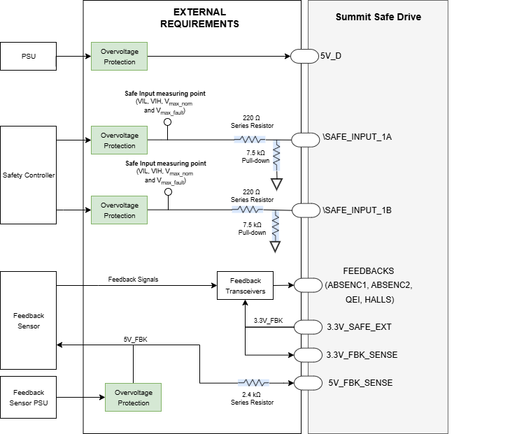
External Requirements for Safe Inputs, Feedback Interface and Logic Supply
The following conceptual diagram summarizes the external requirements for the Safe Inputs and Logic Supply.
Do Not Connect Pins
Integration Requirement | Value | |
|---|---|---|
Do Not Connect Pins | Pin number | 18, 20, 25, 37, 39 and 41 of P2 Interface connector |
Mandatory Requirements |
In order to guarantee the Safety Integrity, pins 16, 18, 37 and 41 of P2 Interface connector must be left unconnected to the Interface board. | |
Application and Environmental Conditions
Functional Safety can only be guaranteed in the following environmental conditions:
Motor Type | Functional Safety is only considered when the drive is controlling three-phase permanent magnet synchronous rotating motors. STO does not apply to DC brush motors. | |
|---|---|---|
Safe Stop |
The STO function stops the torque supplied to the motor, but it continues to move with its own inertia and depending on the related mechanic the motor may even accelerate. It is the responsibility of the customer to prevent any hazards related to this unexpected motor movement.. | |
Uncontrolled Motor Movement |
In the event of a failure in the power stage, the motor shaft may provide torque up to a rotation of 180º electrical degrees. It is the responsibility of the customer to prevent any hazards related to this unexpected motor movement. | |
Reparation | The product is not repairable. After a component fault is detected, the system must be taken out from operation | |
Limited Access | The product must be placed in a limited access environment, so the final user cannot manipulate it without intention. | |
Environmental Conditions | Pollution degree | Pollution degree 2 with an IP54 enclosure installation. |
Over-voltage category | II | |
Altitude | < 2000 m above sea level. | |
Ambient Temperature (Operating) | -20 ºC to 60 ºC | |
Case Temperature (Operating) | -20 ºC to 70 ºC | |
Storage Temperature (Non-Operating) | -40 ºC to 100 ºC | |
Humidity (Operating and Non-Operating) | ≤ 93% (non-condensing) at the Maximum Temperature | |
Vibration | 10 Hz to 150 Hz, 1 g. Test according to EN 60068-2-6:2008: Test Fc | |
Shock | ±5g Half-sine 30 ms Test according to EN 60068-2-27:2009: Shock | |
EMC | Functional Safety has been tested according to EN IEC 61800-3:2018 procedures with the extended ranges of EN 61800-5-2:2017 Annex E. The interface board must meet the same EMC standards (IEC 61800-3:2018 with extended ranges of IEC 61800-5-2:2017). To fulfill the EMC requirements the use of the following elements is required:
| |
Environmental | The interface board must meet the following environmental standards:
| |