Denali XCR Cable Kit - Product Manual
Introduction
This document explains the content and wiring details of the Denali XCR Cable Kit (DEN-CAB). The kit is provided as a tool to speed up the connection between Denali XCR and the user's application.
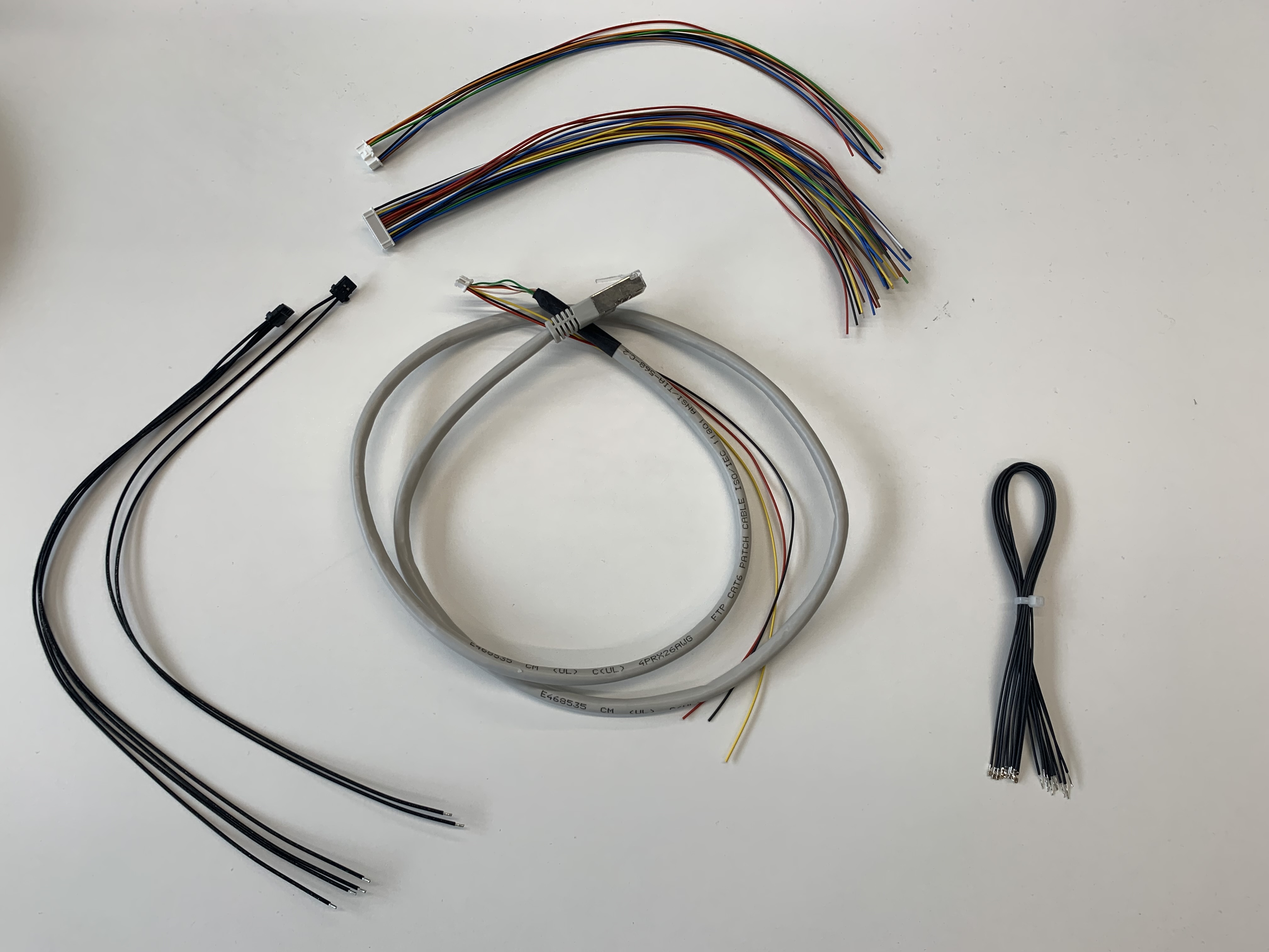
It is composed of the following components:
1 x Power supply cable - 300 mm (C-DEN-PSU)
1 x Input / Output cable - 250 mm (C-DEN-IO)
1 x EtherCAT Communication and Safety cable - 1 m (C-DEN-ECAT)
1 x Feedback cable - 250 mm (C-DEN-FEED)
1 x Motor power cable - 300 mm (C-DEN-CO)
10 x Extra Wires for Feedback & Input / Outputs - 250 mm (C-PC-EXTRA)
Power Supply Cable
The Power supply cable is provided with a length of 300 m. It consists of a set of 2 x 20 AWG cables with a 2pin Molex Pico-lock connector on one side and flying leads on the other. Molex Pico-lock connector should be plugged directly into the XCR P1 connector.
Side 1 - pin | Side 2 - pin | Wire color | Signal | Function |
|---|---|---|---|---|
1 | Flying lead | Black | +V_BUS | Power supply positive |
2 | Flying lead | Black | GND_P | Power supply return |
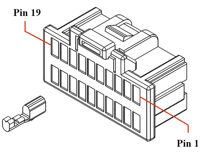
Input / Output Cable
The Input / Output cable is provided with a length of 250 m. It consists of a set of 7 x 28 AWG cables with a 20-pin Molex Pico-clasp connector on one side and flying leads on the other. Molex Pico-clasp connector should be plugged directly into the XCR P2 connector.
The cables are tied by means of spiral wraps in 3 different groups to simplify their identification:
Digital Incremental Encoder
Digital Halls
Absolute Encoder
The pinout of the Feedback cable is as follows:
Side 1 - pin | Side 2 - pin | Wire color | Signal / Label | Function |
|---|---|---|---|---|
1 | Flying lead | Red | +5V_I/O | +5 V 60 mA output, can be used for peripherals such as switches, I/Os, or even supply the safety inputs. |
2 | Flying lead | Black | GND_D | Digital signal ground. |
3 | Flying lead | Orange | IN1 | Digital input 1. 3.3 V logic levels, tolerant to 6 V continuous, can be used with 5 V logic. |
5 | Flying lead | Green | IN2 | Digital input 2. 3.3 V logic levels, tolerant to 6 V continuous, can be used with 5 V logic. |
16 | Flying lead | Black | GND_D | Digital signal ground. |
18 | Flying lead | Blue | CAN_L | CAN bus line dominant low. Pins 17 and 18 are internally connected, can be useful for daisy-chain wiring. |
20 | Flying lead | Brown | CAN_H | CAN bus line dominant high. Pins 19 and 20 are internally connected, can be useful for daisy-chain wiring. |
EtherCAT + Safety Cable
The EtherCAT and Safety cable is provided with a length of 1 m. It consists of a CAT6 (28 AWG - twisted pair & shielded) cable with a 8-pin Molex Pico-clasp connector on one side and a shielded RJ45 connector + flying leads on the other. Molex Pico-clasp connector should be plugged directly into the DEN-XCR P3 connector.
Side 1 - pin | Side 2 - pin | Wire color | Twisted | Signal / Label | Function |
|---|---|---|---|---|---|
1 | Flying lead | Red | - | SAFETY_IN_A | Safe Input A for STO and SBC (positive, active from 5 V to 30 V, ISOLATED). Internal bypass from P3 to P4. |
2 | Flying lead | Black | - | SAFETY_RETURN | Safe Inputs Return common (optocoupler LEDs cathode, ISOLATED). Internal bypass from P3 to P4. |
3 | Flying lead | Yellow | - | SAFETY_IN_B | Safe Input B for STO and SCB (positive, active from 5 V to 30 V, ISOLATED). Internal bypass from P3 to P4. |
4 | 1 | White - Orange | TX_D | TX_D+ | Transmit Data+ line. |
5 | 2 | Orange | TX_D- | Transmit Data- line. | |
6 | 3 | White - Green | RX_D | RX_D+ | Receive Data+ line. |
7 | 6 | Green | RX_D- | Receive Data- line. | |
8 | Shroud / Shield | Drain wire | - | GND_ETH/PE | Connection for the EtherCAT cable shield. This pin is directly connected to the chassis of the drive - PE. To do so it is recommended to use a cable shield termination like TE S02-16-R. |
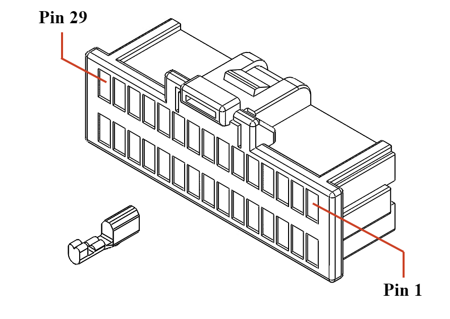
Feedback Cable
The Feedback cable is provided with a length of 250 mm. It consists of a set of 30 x 28 AWG cables with a 30-pin Molex Pico-clasp connector on one side and flying leads on the other. Molex Pico-clasp connector should be plugged directly into the DEN-XCR P5 connector.
Side 1 - pin | Side 2 - pin | Wire color | Signal / Label | Function |
|---|---|---|---|---|
1 | Flying lead | Black | GND_D | Digital ground. |
2 | Flying lead | Blue | MOTOR_TEMP_RET | Motor temperature sensor return (referred to GND_D). Do not use this pin as GND for any other purpose than the negative for motor temperature sensing. |
3 | Flying lead | Orange | ENC_Z- | Differential digital incremental encoder index- input. Leave unconnected if using single-ended encoders. |
4 | Flying lead | Blue | MOTOR_TEMP_IN | Motor temperature sensor input. A 1.65 kΩ pull-up resistor to 3.3 V is included on the drive. |
5 | Flying lead | Green | ENC_Z+ | Differential digital incremental encoder index+ input. |
6 | Flying lead | Black | GND_D | Digital ground. |
7 | Flying lead | Blue | ENC_B- | Differential digital incremental encoder B- input. Leave unconnected if using single-ended encoders. |
8 | Flying lead | Yellow | HALL_3 | Digital hall sensor 3 input, 1 kΩ pullup to 3.3 V included. |
9 | Flying lead | Brown | ENC_B+ | Differential digital incremental encoder B+ input. |
10 | Flying lead | Blue | HALL_2 | Digital hall sensor 2 input, 1 kΩ pullup to 3.3 V included. |
11 | Flying lead | Yellow | ENC_A- | Differential digital incremental encoder A- input. Leave unconnected if using single-ended encoders. |
12 | Flying lead | White | HALL_1 | Digital hall sensor 1 input, 1 kΩ pullup to 3.3 V included. |
13 | Flying lead | White | ENC_A+ | Differential digital incremental encoder A+ input. |
14 | Flying lead | Brown | +3.3V_FEEDBACKS | 3.3V 250mA power supply output for feedbacks. |
15 | Flying lead | Brown | +3.3V_FEEDBACKS | 3.3V 250mA power supply output for feedbacks. |
16 | Flying lead | Brown | +3.3V_FEEDBACKS | 3.3V 250mA power supply output for feedbacks. |
17 | Flying lead | Red | +5V_FEEDBACKS | 5V 500 mA power supply output for feedbacks. |
18 | Flying lead | Red | +5V_FEEDBACKS | 5V 500 mA power supply output for feedbacks. |
19 | Flying lead | Red | +5V_FEEDBACKS | 5V 500 mA power supply output for feedbacks. |
20 | Flying lead | Red | +5V_FEEDBACKS | 5V 500 mA power supply output for feedbacks. |
21 | Flying lead | Brown | ABS1_CLK- | Absolute encoder 1 CLK negative signal output. For single-ended absolute encoders with TTL or CMOS levels leave this pin floating and connect the clock to ABS1_CLK+. |
22 | Flying lead | Brown | ABS2_CLK- | Absolute encoder 2 CLK negative signal output. For single-ended absolute encoders with TTL or CMOS levels leave this pin floating and connect the clock to ABS2_CLK+. |
23 | Flying lead | Blue | ABS1_CLK+ | Absolute encoder 1 CLK positive signal output. |
24 | Flying lead | Blue | ABS2_CLK+ | Absolute encoder 2 CLK positive signal output. |
25 | Flying lead | Yellow | ABS1_DATA- | Absolute encoder 1 DATA negative signal input. For single-ended absolute encoders with TTL or CMOS levels leave this pin floating and connect the signal to ABS1_DATA+. |
26 | Flying lead | Yellow | ABS2_DATA- | Absolute encoder 2 DATA negative signal input. For single-ended absolute encoders with TTL or CMOS levels leave this pin floating and connect the signal to ABS2_DATA+. |
27 | Flying lead | White | ABS1_DATA+ | Absolute encoder 1 DATA positive signal input. |
28 | Flying lead | White | ABS2_DATA+ | Absolute encoder 2 DATA positive signal input. |
29 | Flying lead | Black | GND_D | Digital ground. |
30 | Flying lead | Black | GND_D | Digital ground. |
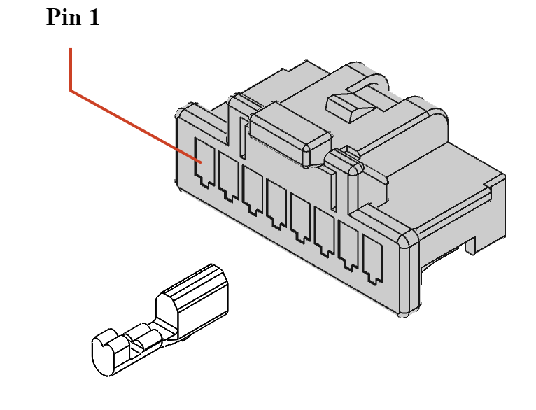
Motor Power Cable
The Motor power cable is provided with a length of 300 mm. It consists of a set of 4 x 20 AWG cables with a 4-pin Molex Pico-lock connector on one side and flying leads on the other. Molex Pico-lock connector should be plugged directly into the DEN-XCR P6 connector.
Side 1 - pin | Side 2 - pin | Wire color | Signal / Label | Function |
|---|---|---|---|---|
1 | Flying lead | Black | PH_C | Motor phase C |
2 | Flying lead | Black | PH_B | Motor phase B |
3 | Flying lead | Black | PH_A | Motor phase A |
4 | Flying lead | Black | PE | Protective earth connection, internally connected to standoffs. |
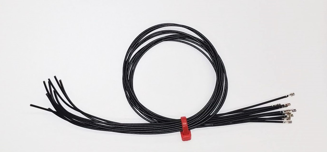
Extra wires for Feedbacks and Input / Outputs (C-PC-EXTRA)
Additionally, a set of 10 x 28 AWG cables with a pre-crimped Molex Pico-clasp socket on one side and flying leads on the other is provided.
These cables could be used to populate any specific functionality not provided in the C-PC-FEED or C-PC-IO connectors.