MCB overview
Motion Control Bus (MCB) is a high-speed serial protocol designed for getting low latency and high determinism in motion control systems where control loops work at high update rates (tens of kHz). It takes elements from different known and reliable industrial protocols such as EtherCAT and CANopen.
Main features
This protocol takes into account the next limiter elements for reaching low latency and high determinism:
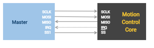
- Physical layer. Based on SPI interface with additional signals for reaching a more efficient communication.
- SPI clock up to 50 MHz
- Full duplex communication
- Decrease latency by using an additional IRQ signal to indicate that a message is ready, avoiding the use of dummy bytes.
- Reduced frame process time. Sometimes the limitation is produced by a complex frame parsing. This time is decreased by applying:
- Fixed frame size. DMA or enhanced buffers can be used efficiently and execution time is more constant.
- Frame fields are as simple as possible.
- Very small header. Determinism and low latency are reached by using small messages. Then data efficiency is kept high using a header as smaller as possible.
- Reliability. Reached by using common CRC checksum and other synchronization strategies from the physical layers.
- MCU peripherals capabilities. The implementation takes into account that most of the market MPU/MCU have the next capabilities on their peripherals:
- SPI peripheral with DMA or enhanced buffers.
- External interrupts.
- Hardware timers.
- Determinism. Reached following a master-slave topology.
Topologies
Single axis configuration
Multi-axis configuration
| Sharing an SPI bus | Independent SPI buses |
|---|---|
|
|
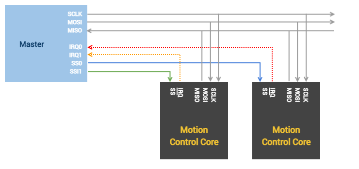
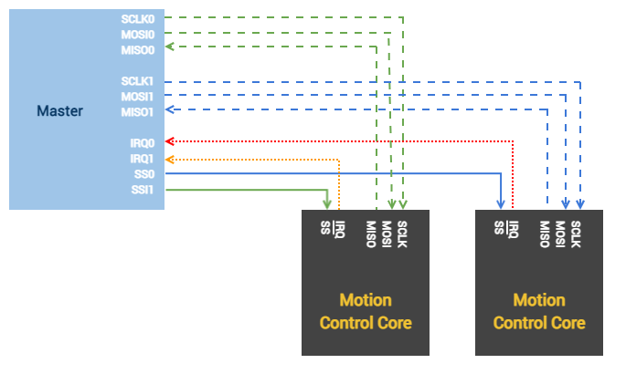
Networks combining independent shared buses are possible too (E.g. 2 independent SPI buses with 2 motion cores on each bus).
MCB state machine
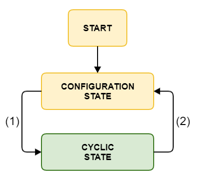
MCB communication has 2 possible states:
- Configuration state. It is reached after power on. In this state, only configuration messages (acyclic) are allowed.
- Cyclic state. When being in cyclic state, there is a cyclic stream of data and also configuration messages (acyclic) are allowed.
The state machine is depicted in the following diagram:
Transitions
| Transition | Description |
|---|---|
| 1 | Enable cyclic state. Cyclic data is configured in the cyclic mapping procedure, and after it is completed successfully, the cyclic state is reached. Cyclic mapping procedure is detailed in MCB Protocol description page. |
| 2 | Return to configuration state. Cyclic data is not sent anymore. Transition is detailed in MCB Protocol description page. |