Safety Manual - Safe Torque Off (STO)
The Safe Torque Off (STO) is a functional safety system that prevents motor torque in an emergency event while Everest CORE remains connected to the power supply. When STO is activated, the power stage is disabled by hardware and the drive power transistors are disconnected, no matter what control or firmware does. The motor shaft will slow down until it stops under inertia and frictional forces. Although not common, in the event of a failure of the power stage during an STO situation, the maximum expected motor movement with torque can be up to 180º electrical degrees. The system must be designed to avoid any hazard in this situation.
If the STO inputs are not energized, the transistors of the power stage are turned off and an STO fault is notified. In order to activate the power stage, and therefore allow the motor operation, the two STO inputs must be energized (high level, typically 5V). STO inputs should not be confused with a digital input configured as enable input, because enable input is firmware controlled and does not guarantee intrinsic safety as it can be reconfigured by a user.
In order to ensure redundancy and safety, the Everest CORE includes 2 separate STO inputs that must be activated or deactivated simultaneously (maximum 1.4 s mismatch). A difference of state between \STO1 and \STO2 inputs will be interpreted as an abnormal situation after 1.4 s the drive will be latched in a fault state. A power supply reset is necessary to remove this STO abnormal error.
Since Everest CORE is a pluggable module intended for being integrated on an electronic interface board, it requires some external electronic components to fulfil the safety requirements:
An external overvoltage protection (or equivalent) is required to limit STO input voltage.
Input current limiter to avoid system destruction in case of internal fault. The current limit can be implemented with a resistor in series.
Input low-state must be guaranteed by means of a pull-down resistor or equivalent (active output). Otherwise, safety function fault tolerance and reaction times, won't be fulfilled.
Safety Function Specifications
Safety Function Specification | Value | |
|---|---|---|
Standards compliance |
| |
Safety function | Safe Torque Off (STO) | |
Safety relevant parameters according to EN 61508:2010 (certification pending) | Safety integrity level | SIL3 |
PFH | 1.22 x 10⁻¹² 1/h | |
SFF | > 99 % (High) | |
Safety relevant parameters according to EN ISO 13849-1:2023 (certification pending) | PL | e |
Category | 3 | |
DC | 99% High | |
MTTFd | ≥ 100 years (High) | |
Safety Function Reaction Time | t < 4.8 ms The Safety Function Reaction time is measured as the time since one of the STO inputs (STO1 or STO2) goes below 0.8 V and the STO function actuates (power transistors deactivated). | |
Fault Reaction Time | t< 4.8 ms The worst-case fault reaction time is on the event of an Abnormal STO. | |
High-demand mode | The EUC (Equipment Under Control) is considered as a high-demand or continuous demand mode system. | |
Mission Time | The mission time of the EUC is of 20 years. | |
Diagnostic Time Interval | In order to guarantee the correct operation of the safety functions, the user has to check the STO function regularly, performing an STO External Diagnostic Test (see further information below). The diagnostic test interval is defined as a minimum of 1 activation per 3 months. | |
Integration Requirements
Functional Safety is only guaranteed within the following Integration Requirements.
Integration Requirement | Value | |
|---|---|---|
STO Interface electrical characteristics | Input pins | \STO1 and \STO2 |
Number of independent channels | 2 | |
Type of Inputs | Digital inputs with ESD protection. Maximum nominal Voltage 7V. Maximum voltage in case of an external overvoltage fault 12 V. | |
Mandatory External Requirements |
See “External Requirements for STO inputs and Logic Supply“ and Application Examples sections below | |
Maximum input LOW level (VIL) | 0.8 V (below this value the STO is ACTIVE, no torque can be applied to the motor) | |
Minimum Input HIGH level (VIH) | 2.5 V (above this value the STO input is inactive, torque can be applied to the motor) | |
Maximum absolute ratings | 7 V max nominal voltage; 12V maximum failure voltage | |
Input current (externally limited) | 50 mA | |
ESD capability | IEC 61000-4-2 (ESD) ± 15 kV (air), ± 8 kV (contact) | |
STO Interface timing characteristics | STO activation time (Safety function Reaction Time) | t < 4.8 ms |
STO deactivation time | t < 2ms | |
Minimum, non-detected STO short pulse | t < 400 µs The Safety controller can transmit short pulses to STOx inputs for diagnostics purposes. These pulses will be ignored by the safety circuit and will not stop the power stage. | |
Abnormal STO diagnostic time | ≤ 4.8 ms (Activation STO) | |
Abnormal STO latching time | 1.4 s ~ 3.4 s (Latching state, permanent activation of STO until power reset) | |
Power supply diagnostic time | 3.3 V over-voltage 200 ns | |
Logic Supply Voltage Range | 5 V ± 2% (nominal range from 4.9 V to 5.1 V; maximum voltage in case of external failure 26.4 V). Safety function is maintained with an overvoltage failure within the specified range, but the other system functions could become non-operational. | |
Logic Supply Connection |
In the event of a failure in the power stage, any logic interface except STO Inputs could become connected to Power Supply. Therefore, even when externally protected with an Overvoltage Protection, any logic interface pin could become connected to a dangerous voltage. For this reason, the STO Inputs (or any other safety-related electronics) cannot share connection with the drive logic (i.e. logic supply) without protection elements in between. See “External Requirements for STO inputs and Logic Supply“ and Application Examples sections below. | |
Power Supply Voltage Range 1 | 48 V SELV (range from 8V to 60V; maximum failure voltage 60 V) | |
Motor Type | STO safety function is only considered when the drive is controlling three-phase permanent magnet synchronous rotating motors. STO does not apply to DC brush motors. | |
Uncontrolled Motor Movement |
Uncontrolled Motor MovementIn the event of a failure in the power stage, the motor shaft may rotate up to 180º electrical degrees. It is responsibility of the customer to prevent any hazards related to this unexpected motor movement. | |
Environmental Conditions for STO2 | Pollution degree | Pollution degree 2 with an IP54 enclosure installation. |
Over-voltage category | II | |
Altitude | < 2000 m above sea level. | |
Operating Temperature | -20ºC to 50 ºC | |
Storage Temperature | -40ºC to 100ºC | |
Vibration | 5 Hz to 500 Hz, 4-5 g. Test according to IEC 60068-2-6:2007-12: Test Fc | |
Shock | ±15g Half-sine 11 msec Test according to IEC 60068-2-27:2008-02: Shock | |
Diagnostics | Internal power supply voltage monitors. Differences between STO1 and STO2 cause abnormal fault. After 1.4 s a hardware latching condition disables the drive until power cycling. Status of STO1, STO2, STO_REPORT, ABNORMAL_FAULT, and SUPPLY_FAULT can be read from the communications. STO firmware notificationA STO stop is notified to the motion controller and creates a fault that can be read externally from any communication interface, however, STO operation is totally independent and decoupled from control or firmware. | |
EMC | Functional Safety has been tested according to IEC 61800-3:2018 procedures with the extended ranges of EN 61800-5-2:2017. The interface board must meet the following EMC standards:
To fulfill the EMC requirements the use of the following elements is required:
| |
Environmental | The interface board must meet the following environmental standards:
| |
1: Although the drive can operate in a wider range of voltages as can be seen in Product Description, the system cannot be considered safe outside this range.
2: The drive can operate outside this range as indicated in the Product Description, however, the system cannot be considered safe as the system reliability and safety margins would not meet the standards.
STO External Diagnostic Test
The operation of the STO diagnostic circuits must be verified at least once per 3 months. The following procedure details a method to verify the correct operation of the STO diagnostic circuits. Note that it is responsibility of the customer to prevent any hazards related to motor movement during this proof test.
The procedure requires the Everest CORE to be connected to a brushless motor.
Procedure Step | Action |
|---|---|
1 | Power on the Everest CORE with STO1 = low, STO2 = low. |
2 | Try to perform a "Motor Enable" (using Motionlab 3 or network commands). |
3 | Verify that the power stage is not enabled by software (a fault should appear) or by hardware (checking the Motor phases voltage with a multimeter). |
4 | Provide STO1 = high, STO2 = low. Remain in this state more than 3.4 seconds. |
5 | Try to perform a "Motor Enable" (using Motionlab 3 or network commands). |
6 | Verify that the power stage is not enabled by software (a fault should appear) or by hardware (checking the Motor phases voltage with a multimeter). |
7 | Provide STO1 = high, STO2 = high. |
9 | Try to perform a "Motor Enable" (using Motionlab 3 or network commands). |
10 | Verify that the power stage is not enabled by software (a fault should appear) or by hardware (checking the Motor phases voltage with a multimeter). |
11 | Shut-down Everest CORE supply and remain in this state for more than 10 seconds. |
12 | Power on the Everest CORE with STO1= low, STO2 = high. Remain in this state more than 3.4 seconds. |
13 | Try to perform a "Motor Enable" (using Motionlab 3 or network commands). |
14 | Verify that the power stage is not enabled by software (a fault should appear) or by hardware (checking the Motor phases voltage with a multimeter). |
15 | Provide STO1 = high, STO2 = high. |
17 | Try to perform a "Motor Enable" (using Motionlab 3 or network commands). |
18 | Verify that the power stage is not enabled by software (a fault should appear) or by hardware (checking the Motor phases voltage with a multimeter). |
19 | Shut-down Everest CORE supply and remain in this state for more than 10 seconds. |
20 | Power on the Everest CORE with STO1= high, STO2 = high. |
21 | Try to perform a "Motor Enable" (using Motionlab 3 or network commands). |
22 | Verify that the power stage can be enabled, allowing motor rotation. Do it by software (system should enter in motor enable state) or by hardware (checking the Motor phases voltage with a multimeter). |
STO Operation States
The truth table of the STO inputs is shown next indicating the different states of the system:
Mode | State | STO1 status / level | STO2 status / level | Power stage status | STO report bit status | STO abnormal fault | State description | ||
|---|---|---|---|---|---|---|---|---|---|
Normal operation | STO Enabled | 0 | < 0.8 V | 0 | < 0.8 V | OFF | 0 | 0 | The system logic is powered, but the STO function is activated. Therefore, no torque can be applied to the motor. STO trip is reported to the MCU and to the safety circuitry. This is intended safe torque off with dual-channel operation. |
Torque enabled (STO inactive) | 1 | > 2.5 V | 1 | > 2.5 V | Can be enabled | 1 | 0 | The STO function is deactivated, and torque can be provided to the motor. The motor can run under firmware control. This is the normal operation state. | |
Abnormal operation |
| 0 | < 0.8 V | 1 | > 2.5 V | OFF | 0 | 1 | If any issue is detected on the dual-channel STO function (their state is different for a long period of time), an abnormal fault is active can be reported. This state avoids the application of torque to the motor. If this persists for > 1.4 s ~ 3.4 s the STO will lock in FAULT state. To reset this fault a power cycle is needed. |
1 | > 2.5 V | 0 | < 0.8 V | OFF | 0 | 1 | |||
Abnormal STO Latched | x | - | x | - | OFF | NOR (STO1, STO2) | 1 | After >1.4 s ~ 3.4 s of abnormal STO active, the driver will stay in this state until the power supply cycle. | |
Abnormal Supply | x | x | x | x | OFF | x | x | If a voltage out of the limits is detected on the internal logic voltages, the system is conducted to a safe state, similar to power-off. Only if the safe logic voltages are recovered (usually after reparation or restart), the system can return to any other state. | |
STO1 and STO2 signals should always change at the same time with a maximum of 1.4 s mismatch. This is necessary to have 2 channel redundancy and allow diagnostics, as a mismatch will cause an abnormal fault.
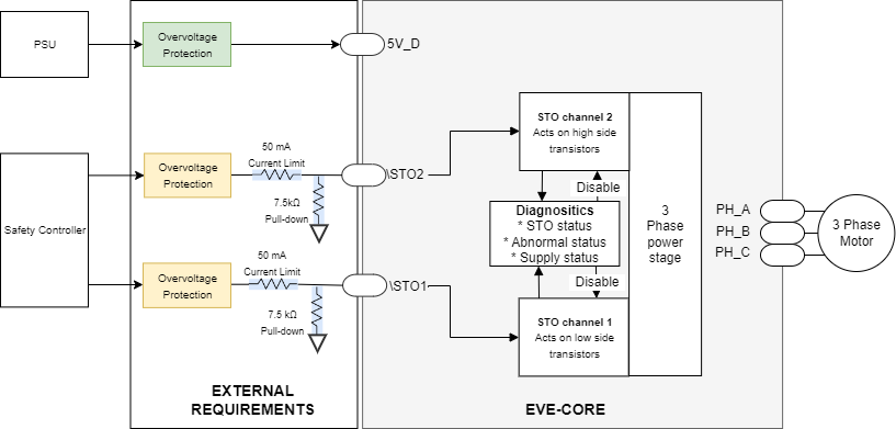
External Requirements for STO inputs and Logic Supply
The following conceptual diagram summarizes the external requirements for the STO inputs and Logic Supply.
Application Examples
The following diagrams provide application examples, which could be further optimized or improved. For further circuit details or assessment, please contact Novanta.
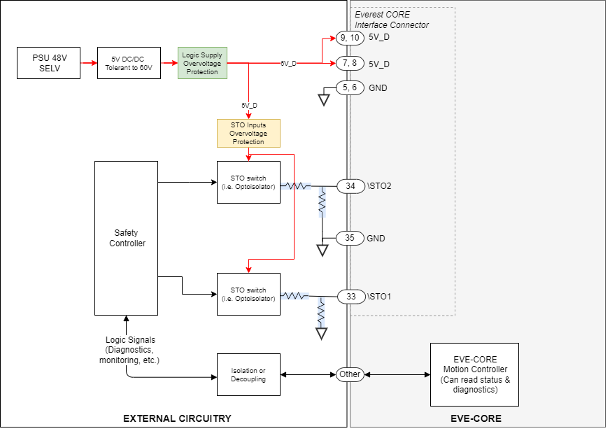
External Requirements Example - 48V PSU
The following diagram depicts an example diagram about how to implement the External Requirements circuitry. This circuit is an example an is not space optimized.
The Logic Supply is protected from failures in the 5V DC/DC by means of the Logic Supply Overvoltage Protection.
The 5V DC/DC is tolerant to 60V input because PSU is SELV and could fail up to 60V.
STO Inputs are overvoltage protected by means of a single STO Inputs Overvoltage Protection (i.e a Voltage Monitor with cut-off capability) who supplies the output switches of an optoisolator.
The STO switch is implemented by means of Optoisolators to decouple the drive from the Safety Controller
The Safety Controller is also decoupled/isolated from the EVE-CORE non-safety-related nets (communications, feedbacks, etc.), which could carry dangerous voltages
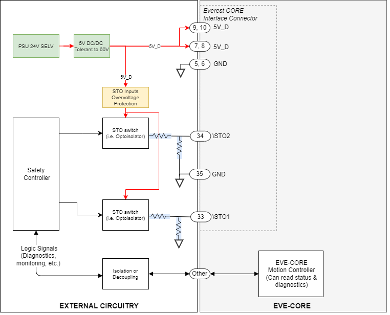
External Requirements Example - 24V PSU
The following diagram depicts an example diagram about how to implement the External Requirements circuitry. This circuit is an example an is not space optimized.
The Logic Supply is generated from a 24V SELV PSU. In case of failures in the 5V DC/DC, the output would be < than 26.4V, and therefore, inside the overvoltage protection range of the Logic supply. For this reason, no additional overvoltage protection is needed.
The 5V DC/DC is tolerant to 60V input because PSU is SELV and could fail up to 60V. If the DC/DC was not tolerant to 60V, then an overvoltage protector would be needed.
STO Inputs are overvoltage protected by means of a single STO Inputs Overvoltage Protection (i.e a Voltage Monitor with cut-off capability) who supplies the output switches of an optoisolator.
The STO switch is implemented by means of Optoisolators to decouple the drive from the Safety Controller
The Safety Controller is also decoupled/isolated from the EVE-CORE non-safety-related nets (communications, feedbacks, etc.), which could carry dangerous voltages
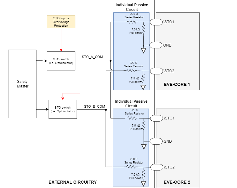
Multiple Drives/Axis connection with a single STO input
The following diagram summarizes how to connect multiple EVE-CORE with a single STO input. It is important to guarantee the Mandatory External Requirements for each EVE-CORE.
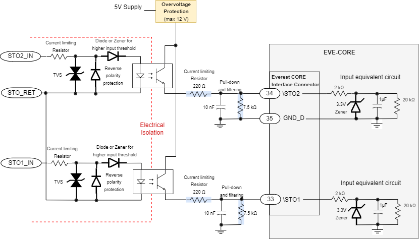
STO Inputs Detailed Interface Circuit
The following diagram shows a suggested circuit for implementing the STO inputs interface.