Inputs and outputs configuration
Summit servo drives include a set of outputs and inputs for general purposes that might be used by the master to extend the functionalities of the application.
Digital Inputs/Outputs
By default, all GPI and GPO are configured to work as standard GPIO. It means that the master is able to:
Read the state of the GPO & GPI
Set the state of the GPO.
Furthermore, the polarity of these GPI & GPO is configurable to simplify the master application. A glitch filter can also be applied to GPI 1, 2, 3 (0x0625 - Digital Inputs 1, 2, & 3 glitch filter) and 4 (0x0626 Digital Input 4 Glitch filter). All digital GPIO registers are listed below.
0x2600 - Digital inputs value - shows the logical digital inputs state
0x2601 - Digital outputs value - shows the logical digital outputs state
0x2602 - Digital outputs set value - allows access to the value of the digital output configured with standard functionality
0x2603 - Digital outputs polarity - allows access to the polarity of the digital outputs
0x2604 - Digital inputs polarity - allows access to the polarity of the digital inputs
0x2625 - Digital inputs 1, 2 & 3 glitch filter - allows access to the glitch filter levels of digital inputs 1, 2, and 3.
0x2626 - Digital input 4 glitch filter - allows access to the glitch filter levels on digital input 4
0x25FC - Map output 1 - allows access to map the functionality of digital output 1
0x25FD - Map output 2 - allows access to map the functionality of digital output 2
0x25FE - Map output 3 - allows access to map the functionality of digital output 3
0x25FF - Map output 4 - allows access to map the functionality of digital output 4
Additionally, these GPI and GPO can be attached to special functionalities that extend the drive capabilities:
Warning
Although it is supported to map an input to different functions, pay special attention to each input mapping. Undesired behaviors could appear due to a poor configuration (i.e. entering quick stop state when enabling a homing switch or limit switch).
Digital Input functionalities
Positive and negative homing switches. A GPI is able to work as a homing switch on applications where this functionality is available. How the homing process works using homing switches is described in the Homing section.
Positive and negative switch limits. A GPI is able to work as a switch limit on applications where the movement is not infinite and delimited by sensors. When this feature is available, the drive will not allow movement in the same direction as the detected switch limit independent of the selected operation mode.
Examples
If a motor is moving into the positive direction and the positive switch limit is "HIGH":
In any of the position modes, the drive will generate a position demand equal to the actual position, so movement is not generated (the position is held).
In any of the velocity modes, the drive will generate a velocity demand equal to 0 (the position is held).
In any of the current modes, the drive will generate a current demand equal to 0 (the position is not held because torque is not applied).
In voltage mode, the drive will generate a voltage demand equal to 0 (the position is not held because torque is not applied).
Quick stop input. A GPI can trigger a quick stop request. When a GPI is mapped to this function and its value is "HIGH" a quick stop transition is executed if possible. See the state machine details (from Operation section) of the drive for further information.
Halt input. A GPI can trigger a Halt request. When a GPI is mapped to this function and its value is "HIGH" a halt request is executed. It behaves exactly the same as the Halt bit of the control word. See the control word register details for further information.
Digital output functionalities
Operation enable indicator. A GPO attached to this event will indicate if the drive is in operation enable state. GPO is set to "HIGH" level when the drive reaches the operation enable state of its state machine. Otherwise, it is set to "LOW".
Health signal. A GPO attached to this event will indicate if the drive is outside the fault state. It is set to "LOW" if a fault is detected and it is active. It is set to "HIGH" otherwise.
External shunt. A GPO attached to this functionality will be set to "HIGH" when the read bus voltage overcomes the shunt enable voltage and will be set "LOW" when the read bus voltage is below the shunt disable threshold.
Check the Shunt braking resistor section for further information.
These functions are linked through the following parameters
Parameter
GPO configured
Map output 1
GPO1
Map output 2
GPO2
Map output 3
GPO3
Map output 4
GPO4
Analog Inputs
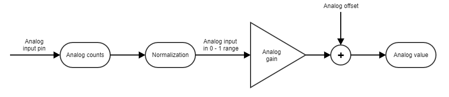
Summit series have a set of general purpose analog inputs that can be simply read and sent to a master through communications or they can be used for debugging purposes.
The analog inputs can be configured with a gain and offset to adapt their value to the desired range and units, depending on the purpose they will serve. On a normal basis, the analog readings will be unitary (0 (minimum readable voltage) to 1 (maximum readable voltage)) when gain is 1 and offset is 0. The following parameters can be used to configure the analog input readings:
Analog 1 gain: Multiplies the unitary analog input 1 reading to match a specific value range.
Analog 1 offset: Displaces the analog input 1 reading (after applying Analog gain) to center it on a specific value.
Analog 1 value: Shows analog input 1 value in user units after gain and offset application.
Analog 1 counts: Shows analog input 1 raw ADC counts.
Analog 2 gain: Multiplies the unitary analog input 2 reading to match a specific value range.
Analog 2 offset: Displaces the analog input 2 reading (after applying Analog gain) to center it on a specific value.
Analog 2 value: Shows analog input 2 value in user units after gain and offset application.
Analog 2 counts: Shows analog input 2 raw ADC counts.
Note
Analog inputs are sampled at the same rate as the current control loop.