LED signals reference
LED signals definitions
LED state | Description |
|---|---|
On | The LED is constantly on. |
Off | The LED is constantly off. |
Flickering | The LED flickering will have an On and Off sequence with a frequency of approximately 10 Hz: on for approximately 50 ms and off for approximately 50 ms. 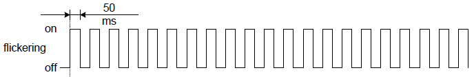 |
Blinking | The LED blinking will have an On and Off sequence with a frequency of approximately 2,5 Hz: On for approximately 200 ms followed by Off for approximately 200 ms. 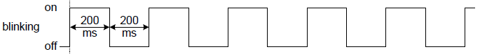 |
Single flash | The LED will have a short flash (approximately 200 ms) followed by a long off phase (approximately 1000 ms). 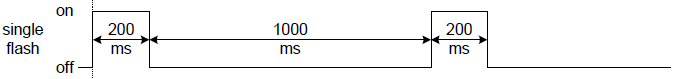 |
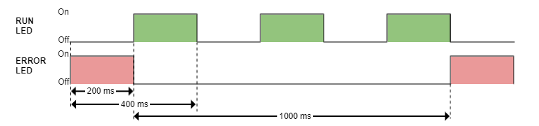
Double flash | The LED will have a sequence of two short flashes (approximately 200 ms), separated by an off phase (approximately 200 ms). The sequence is finished 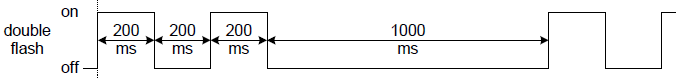 |
Triple flash | The LED will have a sequence of three short flashes (approximately 200 ms), separated by an off phase (approximately 200 ms). The sequence is finished 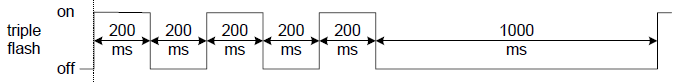 |
LED signals
LED signal | Meaning |
|---|---|
FAULT LED (Red) | Signals if the drive is in fault state. See State Machine in Operation section and Error management section for further information.
|
EtherCAT
In EtherCAT firmware, LED signals are described by the following table:
LED signal | Meaning | ||
|---|---|---|---|
RUN LED (Green) | Provides information about the EtherCAT network state machine, according to EtherCAT specification. | ||
LED State | EtherCAT slave status | ||
Off | INIT | ||
Flickering | BOOTSTRAP | ||
Blinking | PRE-OPERATIONAL | ||
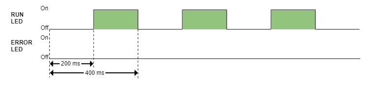
Single Flash | SAFE-OPERATIONAL | ||
On | OPERATIONAL | ||
ERROR LED (Red) | Provides information about the EtherCAT communication status, according to EtherCAT specification. | ||
LED state | EtherCAT slave status | ||
Off | No error | ||
Blinking | Invalid configuration | ||
Single flash | Local error | ||
Double flash | Watchdog timeout | ||
LINK0 & LINK1 | Provide information about the Ethernet Link Status in each port. | ||
LED state | EtherCAT slave status | ||
On | Port closed | ||
On-Off alternating | Port opened (activity on port) | ||
Off | Port opened (no activity on port) | ||
CANopen
In CANopen firmware, LED signals are described by the following table:
LED signal | Meaning | ||
|---|---|---|---|
RUN LED (Green) | Provides information about the CANopen network state machine, according to CiA 303-3 specification. | ||
LED state | CANopen slave status | ||
Off | Device is switched off | ||
Blinking | PRE-OPERATIONAL | ||
Single Flash | STOPPED | ||
On | OPERATIONAL | ||
ERROR LED (Red) | Indicates the status of the CAN physical layer and errors due to missed CAN messages. | ||
LED state | Event | Description | |
Off | No error | Device is in working condition. | |
Single flash | Warning limit reached | At least one of the error counters of the CAN controller has reached or exceeded the warning level (too many error frames). | |
Double flash | Error control event | A guard event (NMT-slave or NMT-master) or a heartbeat event (heartbeat consumer) has occurred. | |
Triple flash | Sync error | The sync message has not been received within the configured communication cycle period time out. | |
On | Bus off | The CAN controller is in bus off state. | |
LINK0 & LINK1 | Provide information about the Ethernet Link Status in each port. | ||
LED state | Port state | ||
Off | Port closed | ||
On-off alternating | Port opened (activity on port) | ||
On | Port opened (no activity on port) | ||
|
In Everest (EVE) and related products, both Ethernet ports are available and they act as an Ethernet switch. In CAP, DEN, EVS and related products, only Ethernet 1 is available, so only LINK1 signal is present. | |||
LEDs at start-up & Troubleshooting
After powering on, some of the LED signals can help troubleshoot.
EtherCAT
Typical behaviour
If EtherCAT cables are connected on Port 0/1, Link LEDs will light according to the definition.
EtherCAT firmware will start with no other LED because the slave will stay in INIT State after power-up until an EtherCAT master forces it to transition to another state.
| LED signal | Start-up behaviour |
|---|---|
| RUN LED (Green) |
|
| ERROR LED (Red) |
|
| RUN & ERROR LED |
|
| FAULT LED (Red) |
|
The rest of the LED signals follow the standard behavior.
CANopen
| LED signal | Start-up behavior |
|---|---|
| RUN LED (Green) |
|
| ERROR LED (Red) |
|
| RUN & ERROR LED |
|
| FAULT LED (Red) |
|
The rest of the LED signals follow the standard behaviour