Commutation
To understand this document, it is highly recommended to have some knowledge about Field Oriented Control algorithm. Take a look at this application note.
Contents
What is commutation and why is it necessary?
The phase currents in the motor windings create a magnetic field that interacts with the magnetic field of the motor magnets. Commutation is the process by which these phase currents are generated with the intention of applying the highest torque in the most efficient manner. This is needed to successfully control the motor's movement. Some types of motor have intrinsic commutation processes, such as brushed motors, in which the built-in brushes makes the winding currents change. On the other hand, with brushless permanent magnet motors, servo drives require information about the rotor position to achieve this.
Rotor information can be extracted directly from position sensors in the motor, or inferred from other physical phenomena via sensor-less algorithms. Generally position sensors in the motor provide information about mechanical rotation (with some exceptions such as the digital hall sensors). However the information required by the servo drive is the rotor position within two opposite magnet poles, rather than a mechanical rotation. From now on, this will be called electrical angle in this document. A permanent magnet motor may have more than one pole pair, thus the electrical angle is derived by multiplying the mechanical rotation readings by the pole pairs of the motor
From now on in this document, the position sensor used to determine the electrical angle of the motor will be called commutation sensor.
What is alignment and why is it necessary?
Generally, the electrical angle measured by the commutation sensors does not match the servo drive's coordinate system. In other words, when the servo drive generates a current vector pointing at a specific electrical angle in the driver's coordinate system, the rotor tends to align to that specific electrical angle, somewhere between two opposite magnet poles. The angle readings retrieved from the commutation sensor are normally misaligned with respect to the applied electrical position. This can be caused by how the commutation sensor is physically mounted, or by how the phases are wired.
Alignment is the process by which the servo drive calculates and compensates the offset between the angle readings from the commutation sensor and the driver's coordinate system. This ensures that the driver can have the correct rotor position information at all times, and that it is coherent with the driver's coordinate system, allowing it to move the motor in a controlled manner.
Every time an alignment procedure is performed, an angle offset is calculated and applied to the commutation sensor readings.
Commutation sensor types
Commutation sensors can be split into two main categories. Different alignment procedures are required based on the type of commutation feedback mounted in the system.
Incremental sensors. Incremental sensors only provide information of the displacement of the motor once the driver and the sensor are fully powered up and functional. After each power cycle, the angle value reported by these sensors is completely unreliable and an alignment procedure is required every time. Incremental encoders are included in this category.
Absolute sensors: Absolute sensors always provide the same information for a given rotor position regardless of the state of the driver, even after a driver power cycle or after a sensor power loss. BiSS-C / SSI absolute encoders, magnetic encoders, and digital halls are included in this category. Once the misalignment of these sensors is known, this information can be used indefinitely to keep track of the rotor position.
Alignment procedures
Alignment procedures define a series of steps to calculate and compensate the commutation sensor's offset or misalignment with the system. Different alignment procedures are available for different scenarios and they depend on the type of commutation sensor used. The available alignment procedures are described below.
No alignment
This procedure simply retrieves an angle offset from the servo drive's memory and applies it. It is useful when the misalignment between the commutation sensor and the driver are known beforehand. This procedure is intended to be used with absolute sensors only. In this case, the commutation angle offset is not modified in the driver, only read.
Forced alignment
This alignment procedure is used to calculate the commutation sensor angle offset with the minimum possible movement. To do this, the driver forces a series movements in the motor in order to estimate the electrical angle of the rotor. Once this is known, the system can calculate and apply commutation angle offset so that the motor can be controlled correctly. This alignment procedure can be used with any type of sensor. The algorithm by which the forced alignment determines the rotor's angle is described below
Binary search
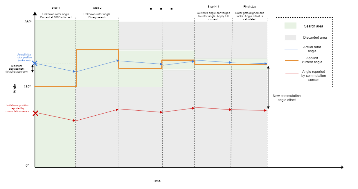
The objective of this method is to determine the electrical angle at which the rotor is located while causing the smallest possible rotor movement. This algorithm generates a sequence of currents pointed at a specific electrical angle inside the D-Q vector space. Based on measured rotor displacement, the injected electrical angle is modified following a binary search logic, thus making it converge into the actual electrical rotor position. The binary search algorithm is described in the following steps:
To begin with, the initial rotor angle is read from the commutation sensor
Phase currents are applied at 180 electrical degrees (the middle of the whole electrical angle range). If the rotor is not perfectly aligned to this position, it will experience some amount of torque and it will begin to move. The amount of movement depends on the configured maximum current for this procedure.
The servo driver continuously reads the commutation sensor and calculates the displacement from initial angle reading (latched during step 1). This process continues until this displacement exceeds a certain distance, defined by the alignment accuracy parameter
If the rotor moves far enough from its initial position, the applied electrical angle is modified in the following way.
We don't have a way to export this macro.The electrical angle measured at this moment is now stored as the new initial rotor angle. By iterating through steps 2 to 5, the search narrows down and the injected angle converges to the actual rotor angle.
After some iterations, the injected angle is considered to have converged (approximately) to the actual rotor position. At this point, the maximum allowed current is applied in this direction and the rotor locks to this position. Once the rotor is steady, the misalignment between the injected angle and the readings of commutation sensor is calculated and copied to the commutation angle offset parameter.
Note
The binary search alignment method modifies some of the feedbacks internally to perform the alignment. If the alignment procedure is either interrupted or finished, the feedback configuration of the user is restored.
Non-forced alignment
To calculate the commutation sensor's misalignment, a second feedback is used as a reference. The reference sensor must be an absolute sensor and must be previously configured and aligned to the driver's coordinate system. During this procedure, the driver will perform the commutation using the reference sensor but will switch to the selected commutation sensor once its misalignment has been calculated. This happens on an update of the reference sensor's readings (for example, on a digital halls transition).
Example
A system is made up of a brushless motor with an incremental encoder as commutation sensor and digital halls as a reference sensor. On power up, the incremental encoder readings are completely unrealiable, so the non-forced alignment procedure is done:
The system begins to use the digital halls for commutation. The digital halls are already aligned with the servo drive and have their own reference sensor offset configured. The system stops using the digital halls for commutation once a transition is detected in the digital hall signals.
In that moment, the offset between the digital halls and the incremental encoder is computed. The offset is applied to the commutation angle offset.
After the commutation angle offset has been applied, the device performs commutation with the incremental encoder.
Warning
The reference sensor must be aligned with the system prior to a non-forced alignment
After a forced alignment, the calculated offset is automatically copied to the reference sensor offset
When is alignment executed?
The alignment procedure is executed in the following scenarios (regardless of which procedure is selected):
On the first transition to operation enabled state. If the alignment procedure is aborted before it has been able to complete (for example by exiting operation enabled state before completion), it will be re-tried on the next transition to operation enabled
On a transition to operation enabled state whenever the commutation feedback sensor or the reference feedback sensor have been written to.
When can alignment be skipped?
Alignment can be skipped (by selecting the No alignment procedure) when all of the following conditions are met:
The commutation feedback is an absolute encoder
The commutation angle offset is known beforehand (ideally, a forced alignment has been performed at some point in the past)
The motor and motor pole pairs remain identical.
The phase wiring remains identical.
The commutation feedback's mechanical mounting and alignment remains the same.
Commutation parameters
The following parameters are used to configure the commutation of the driver
Motor pole pairs. Number of magnet pole pairs in the motor. Since the commutation sensor normally returns a measurement of mechanical rotation of the motor, this parameter is used to convert the mechanical angle readings to electrical angle readings.
Commutation feedback sensor. Selects the type of feedback used for commutation
Warning
Only four feedbacks can be mapped simultaneously in all of the feedback sensor parameters
Commutation angle offset. Defines the angle misalignment in unitary values (0.0 for 0 degrees and 1.0 for 360 degrees) between the commutation sensor readings and the driver's coordinate system.
Note
This parameter is automatically modified by Forced and Non-forced alignment procedures. However it can be overwritten by the user
Commutation angle value. This parameter contains the electrical angle in unitary values (0.0 for 0 degrees and 1.0 for 360 degrees) read by the commutation feedback sensor once the pole pairs and commutation angle offset have been applied.
Alignment parameters
The following parameters are used to configure the alignment procedure
Alignment mode. Selects which alignment procedure will be executed.
Max. current on alignment sequence. Maximum current to be used by the forced alignment procedure.
Alignment accuracy. This register defines the minimum distance in millidegrees (electrical) that the rotor should move for the binary search algorithm to move forward. It is also used to determine how many steps the binary search will run. The binary search algorithm ends when the search area of the binary search algorithm is limited in each direction by
We don't have a way to export this macro.Example
Setting a value of 10000 millidegrees means that the actuator must physically move 10 electrical degrees in each step and the number of steps will be 4:
- Last angle search area shall be: ±3 · Alignment accuracy = ±30 º
- First search area is ±180 º > 30º
- Second search area is ±90 º > 30 º
- Third search area is ±45º > 30º
- Fourth (last) search area is ±22,5º < 30 º
Special case
When aligning digital halls, the minimum measurable angle is 60 degrees. The alignment accuracy must be configured to a value higher than 60000 mº. In this case the algorithm is modified to generate two steps multiple of 60º:
- First search area is 240º
- Second (last) search area is 120º
Alignment timeout. This timeout is used to abort the forced alignment and expires if the displacement of the actuator is less than value introduced in the alignment accuracy parameter. If this happens, the next injected angle is generated assuming a positive displacement.
Note
During the last step, the Max. current on alignment sequence is injected during the time specified in Alignment timeout to ensure proper rotor alignment to the estimated rotor angle
Reference feedback. Selects the type of feedback used as reference for the non-forced alignment.
Warning
Only four feedbacks can be mapped simultaneously in all of the feedback sensor parameters
Reference angle offset. Defines the angle misalignment in unitary values (0.0 for 0 degrees and 1.0 for 360 degrees) between the reference sensor readings and the driver's coordinate system.
Note
This parameter is automatically modified by the Forced alignment procedure. However it can be overwritten by the user
Reference angle value. This parameter contains the electrical angle in unitary values (0.0 for 0 degrees and 1.0 for 360 degrees) read by the reference feedback sensor once the pole pairs and reference angle offset have been applied.
Which parameters are modified by alignment procedures?
Forced alignment modifies the commutation angle offset and the reference angle offset.
Non-forced alignment modifies the commutation angle offset.
No alignment doesn't modify any parameters.
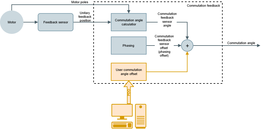
User commutation angle offset
The 0x2042 - User Commutation Angle Offset (PDO mappable) allows users to compensate external factors affecting motor phasing. This offset modifies the 0x040 - Commutation angle value as shown in the figure below: