Connectors Guide
Connector Overview
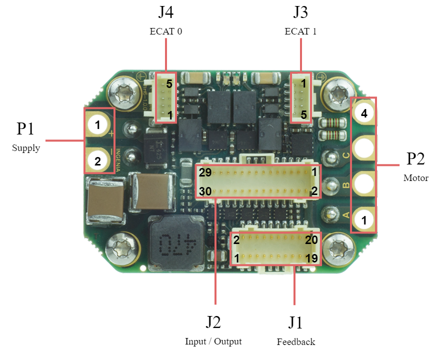
Supply
Drive Supply Protection Requirement
On power up, it is essential that the input voltage to the drive is below 4V if executed soon after a power down.
Note that this is a requirement for both single and dual power supply. For dual power supply, both the main and the logic power supply must be below 4V before a new power up is executed. Please note that the time required for the drop to 4V might be different for the main and the logic supply input.
The time required for the voltage to drop below 4V is application specific and can be estimated experimentally with the use of an oscilloscope with the probe placed at the input to the drive.
Battery Powered Applications
Many battery powered applications have a switch or a relay integrated between the battery and the drive. This scenario might cause the voltage to bounce on power on. The voltage can drop to values that can damage the drive (please refer to the minimum input voltage of the drive within the Product Specification manual of your drive).
In such cases, we advise adding a capacitor between the switch/relay and the drive. This will smoothen the voltage input on power on.
The capacitance is application specific and can be estimated experimentally. It is important for the capacitance to be dimensioned in a way that the voltage does not drop below the minimum input voltage of the drive + 0.5V.
P1 connector | |||
|---|---|---|---|
2.6 mm diameter gold plated solder pads or flying leads option. Pad pitch is 5.08 mm. | |||
Pin | Signal | Function | Warning! Risk of electric shock!  |
1 | POW_SUP | Power supply positive | |
2 | GND_P | Power supply return | |
Notes | |||
Warning, power supply and motor terminals can have dangerous voltages in excess to 50 V and cause electric shock. Never touch them directly while in operation. The end installation must ensure that these terminals are not accessible. Recommended section wire is 2.5 mm2 ~ 8.4 mm2 , AWG 13 ~ AWG 8. High-temperature materials are necessary (≥ 180 ºC). See Wiring and Connections - Power Supply and Motor Power for more detailed information about the required wire section. Adapt the cable diameter to the worst-case current needs. It is recommended to use flexible silicone or Teflon cables with high-temperature ratings ≥ 180 ºC. The diameter of the cable jacket (insulator) should be less than 5.08 mm to prevent collision between wires. The cables must always be mechanically secured after soldering. When using power supply only (no logic supply) it is recommended to connect pins 27 (+LOG_SUP) and 29 (GND_D) of I/O connector J2 together. | |||
Motor
P2 connector | |||
|---|---|---|---|
2.6 mm diameter gold plated solder pads or flying leads option. Pad pitch is 5.08 mm. | |||
Pin | Signal | Function | Warning! Risk of electric shock! |
1 | PH_A | Motor phase A | |
2 | PH_B | Motor phase B | |
3 | PH_C | Motor phase C | |
4 | PE | Protective earth connection, internally connected to standoffs and drive housing. | |
Notes | |||
Warning, power supply and motor terminals can have dangerous voltages in excess to 50 V and cause electric shock. Never touch them directly while in operation. The end installation must ensure that these terminals are not accessible. Recommended section wire is 2.5 mm2 ~ 8.4 mm2 , AWG 13 ~ AWG 8. High-temperature materials are necessary (≥ 180 ºC). See Wiring and Connections - Power Supply and Motor Power for more detailed information about the required wire section. The cables must be mechanically secured after soldering. For long cables, it is essential to use a shielding connected to protective earth at both ends of the cable. | |||
Feedback Connector
J1 connector | ||
|---|---|---|
20 pins 2 row Pico-Clasp 1 mm pitch header. Molex 501190-2027 | ||
Pin | Signal | Function |
1 | +5V_OUT | 5 V 200 mA total max. Pins 1, 9, 14 are internally connected. |
2 | GND_D | Digital signal ground |
3 | ENC_A+/DATA2+ | Differential digital incremental encoder: A+ input Single-ended digital incremental encoder: A input Absolute encoder 2: Data + |
4 | ENC_B+ | Differential digital incremental encoder: B+ input Single-ended digital incremental encoder: B input |
5 | ENC_A-/DATA2- | Differential digital incremental encoder: A- input Single-ended digital incremental encoder: Leave unconnected Absolute encoder 2: Data - |
6 | ENC_B- | Differential digital incremental encoder: B- input Single-ended digital incremental encoder: Leave unconnected |
7 | ENC_Z+/CLK2+ | Differential digital incremental encoder: Index+ input Single-ended digital incremental encoder: Index input Absolute encoder 2: Clock + |
8 | ENC_Z-/CLK2- | Differential digital incremental encoder: Index- input Single-ended digital incremental encoder: Leave unconnected Absolute encoder 2: Clock - |
9 | +5V_OUT | 5 V 200 mA total max. Pins 1, 9, 14 are internally connected. The 5V supply could be deactivated by FW to reduce power consumption. |
10 | GND_D | Digital signal ground |
11 | HALL_1 | Digital hall sensor input 1 |
12 | HALL_2 | Digital hall sensor input 2 |
13 | HALL_3 | Digital hall sensor input 3 |
14 | +5V_OUT | 5 V 200 mA total max. Pins 1, 9, 14 are internally connected. The 5V supply could be deactivated by FW to reduce power consumption. |
15 | GND_D | Digital signal ground |
16 | DATA1+ | Absolute encoder 1 DATA positive signal input |
17 | CLK1+ | Absolute encoder 1 CLK positive signal output |
18 | DATA1- | Absolute encoder 1 DATA negative signal input. For single-ended absolute encoders with TTL or CMOS levels leave this pin floating and connect the signal to DATA+. |
19 | CLK1- | Absolute encoder 1 CLK negative signal output. For single-ended absolute encoders with TTL or CMOS levels leave this pin floating and connect the clock to CLK+. |
20 | PE | Protective earth connection, internally connected to standoffs and drive housing. For systems where the drive is not integrated inside the motor, the PE pin should typically be connected to the feedback cable shield to protect it against electromagnetic interferences. To do so it is recommended to use a cable shield terminator like TE S02-16-R. |
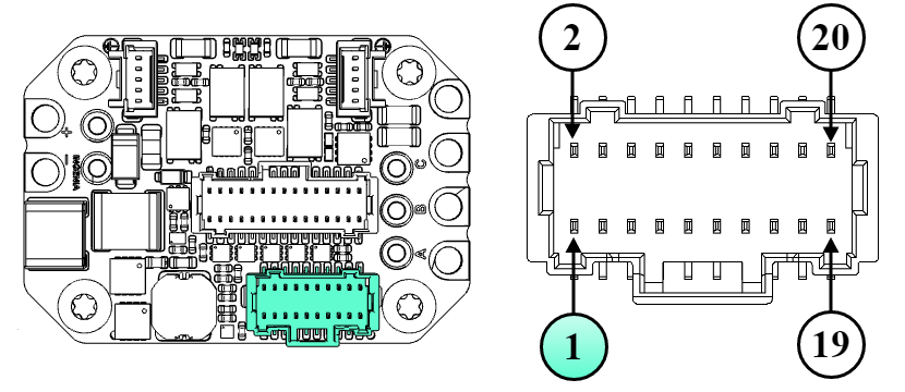
Input / Outputs Connector
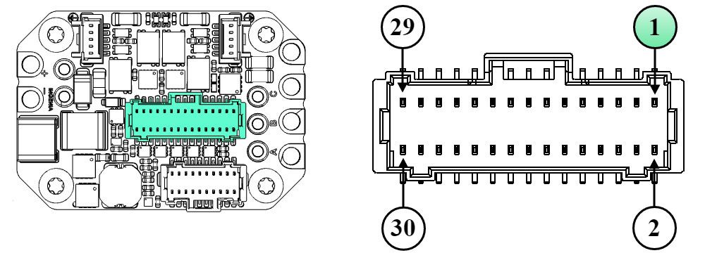
J2 connector | ||
|---|---|---|
30 pins 2 row Pico-Clasp 1 mm pitch header. Molex 501190-3017 | ||
Pin | Signal | Function |
1 | STO_1 | Safe Torque Off input 1 (positive, active from 5 V to 24 V, ISOLATED) |
2 | PE | Protective earth connection, internally connected to standoffs and drive cold plate. Can be used to connect cable shield. To do so it is recommended to use a cable shield terminator like TE S02-16-R. |
3 | STO_RET | Safe Torque Off common (optocoupler LEDs cathode, ISOLATED). |
4 | +5V_OUT | +5 V output. The 5V supply could be deactivated by FW to reduce power consumption. |
5 | STO_2 | Safe Torque Off input 2 (positive, active from 5 V to 24 V, ISOLATED) |
6 | GND_D | Digital signal ground |
7 | NC | Intentionally not connected. |
8 | +5V_OUT | +5 V output. |
9 | CAN_H | CAN bus line dominant high |
10 | RESERVED | Reserved |
11 | CAN_L | CAN bus line dominant low |
12 | /BOOT | This pin can be pulled down to GND_D to force enter boot mode during power-up. Typically not necessary. If not used, always leave it unconnected |
13 | GND_D | Digital signal ground |
14 | IN1 | Digital input 1 (5V levels) |
15 | IN2 | Digital input 2 (5V levels) |
16 | IN3 | Digital input 3 (5V levels) |
17 | IN4 | Digital input 4 (5V levels) |
18 | OUT1 | Digital output 1 (5V levels) |
19 | OUT2 | Digital output 2 (5V levels) |
20 | OUT3 | Digital output 3 (5V levels) |
21 | OUT4 | Digital output 4 (5V levels) |
22 | AN1+ | Analog input 1 positive (±10V range) |
23 | BRAKE_OUT | Brake output (open-drain transistor with PWM capability). A freewheeling diode anode is connected to this pin. |
24 | AN1- | Analog input 1 negative (±10V range). Connect to GND if a single-ended analog input is used. |
25 | BRAKE_DIODE_K | The cathode of the freewheeling diode for the brake should be connected to the power supply of the brake. The anode of the diode is connected to pin 23 (BRAKE_OUT). |
26 | GND_D | Digital signal ground |
27 | +LOG_SUP | Logic supply positive. Providing the logic supply is optional as the drive is automatically powered from the DC bus on its full operating voltage range. Logic supply can be used to keep communications alive while the power bus is off. Powering the logic from this input at 12 V or 24 V reduces overall standby losses and drive self-heating since the main DC/DC converter of the drive has better efficiency at lower voltages. |
28 | MOTOR_TEMP | Motor temperature sensor input. A 1.65 kΩ pull-up resistor to 5 V is included on the drive. |
29 | GND_D | Digital signal ground, logic supply negative |
30 | MOTOR_TEMP_RET | Motor temperature sensor return (referred to GND_D). Do not use this pin as GND for any other purpose than the negative for motor temperature sensing. |
EtherCAT Connectors
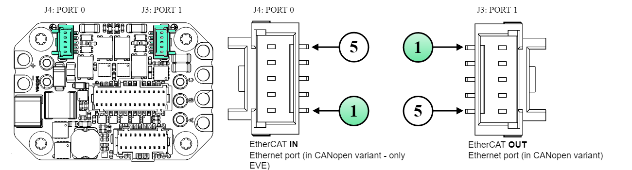
J3 & J4 connectors | ||||
|---|---|---|---|---|
5 pins 1 row Pico-Clasp 1 mm pitch header. Molex 501940-0507 | ||||
Pin | Signal | Function | Suggested pinout M12-4 D-coded | Suggested pinout RJ45 |
1 | TX_D+ | Transmit Data+ line. Colour typ.: White - Orange | 1 | 1 |
2 | TX_D- | Transmit Data- line. Colour typ.: Orange | 3 | 2 |
3 | RX_D+ | Receive Data+ line. Colour typ.: White - Green | 2 | 3 |
4 | RX_D- | Receive Data- line. Colour typ.: Green | 4 | 6 |
5 | GND_ETH/PE | Connection for the EtherCAT cable shield. This pin is directly connected to the chassis of the drive - PE. To do so it is recommended to use a cable shield termination like TE S02-16-R. | Housing / Shield | Shroud / Shield |
Note | ||||
Both network connectors have the same pinout, thanks to auto-negotiation there is no need to make crossed-cables. I.e. TX+ of one device can be connected to TX+ of another. Note that port 0 should be used as EtherCAT IN and port 1 as EtherCAT OUT. | ||||
Mating Connectors
J1 mating connector | |
|---|---|
Description | Molex Pico-Clasp™ 1.0 mm pitch 20 positions dual row receptacle with locking ramp |
Image (Reference only. Please verify with supplier's datasheet) | 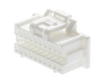 |
Part number | |
J2 mating connector | |
|---|---|
Description | Molex Pico-Clasp™ 1.0 mm pitch 30 positions dual row receptacle with locking ramp |
Image (Reference only. Please verify with supplier's datasheet) | 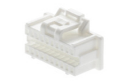 |
Part number | |
J3 & J4 mating connectors with latch holder | |
|---|---|
Description | Molex Pico-Clasp™ 1.0 mm pitch 5 positions single row receptacle with Latch Holder. Provides stronger locking performance and is easy to extract. Use this connector in case the wiring ensures no strong pull will be performed to the cables, this could cause damage to the PCB connector. |
Image (Reference only. Please verify with supplier's datasheet) | 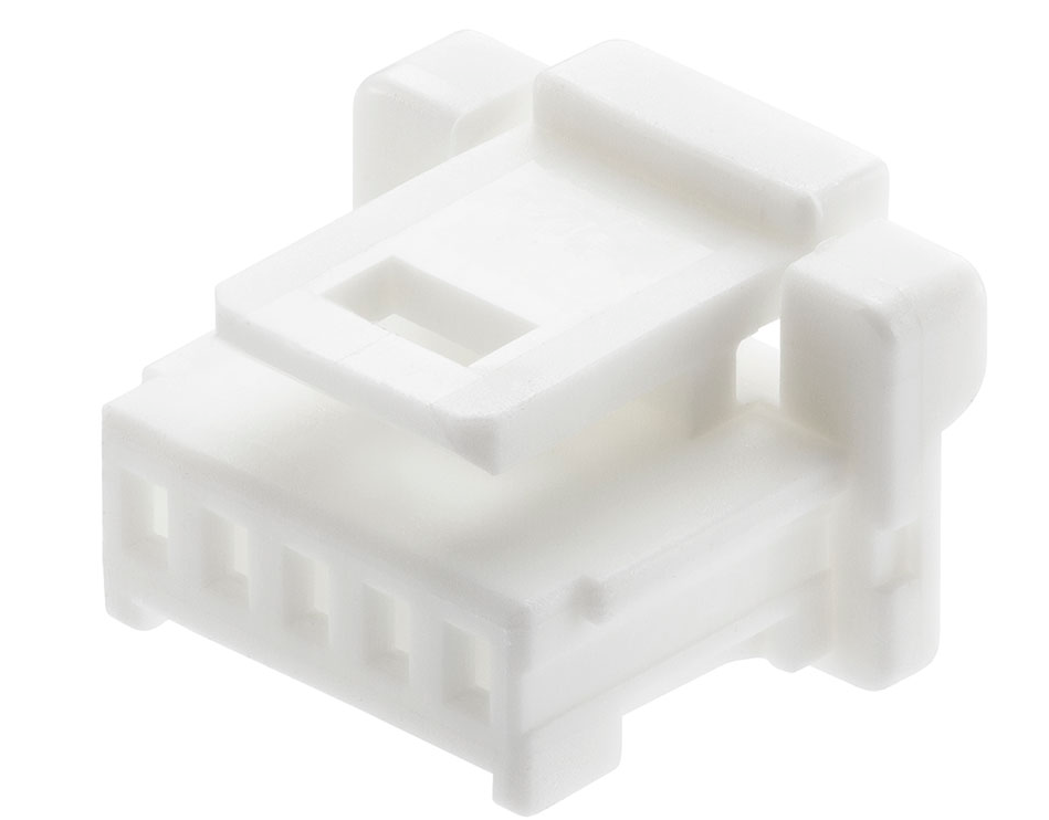 |
Part number | |
J3 & J4 mating connectors with locking ramp | |
Description | Molex Pico-Clasp™ 1.0 mm pitch 5 positions single row receptacle with locking ramp. Provides less strong locking compared to the latch holder but will avoid breaking the PCB connector in case of strong pull. |
Image (Reference only. Please verify with supplier's datasheet) | 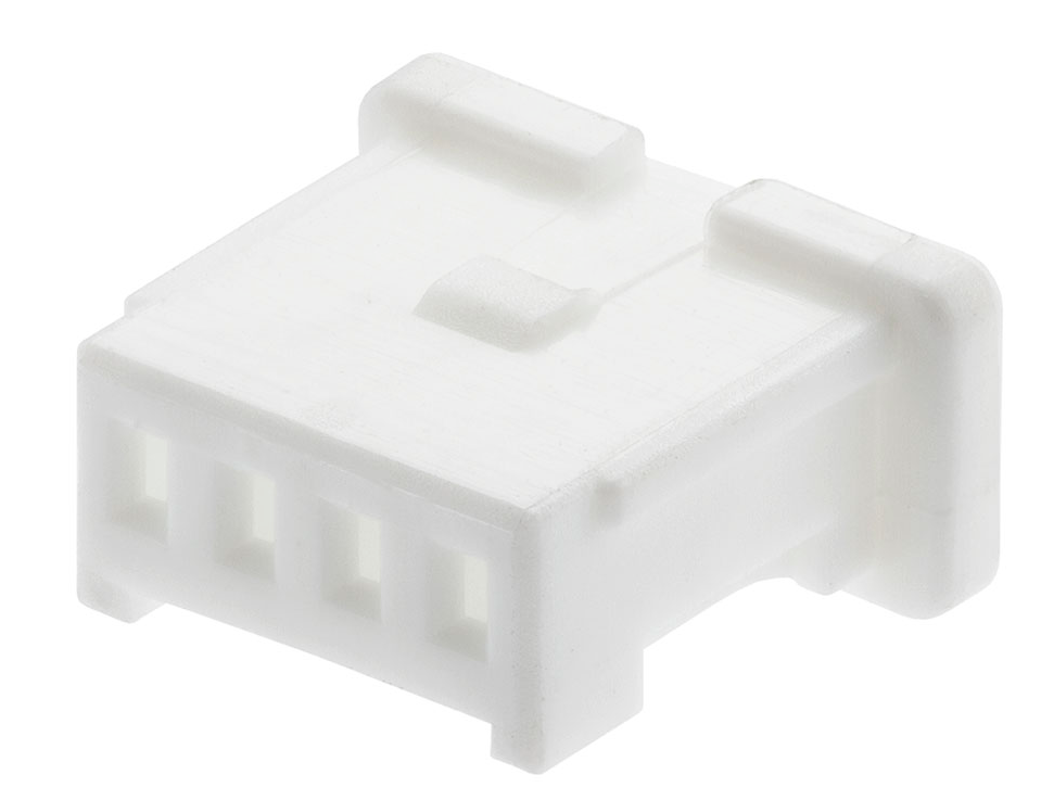 |
Part number | |
Common mating terminals and cables for all signal connectors
All signal connectors are of Molex Pico-Clasp™ family. All share the same crimp terminals and jumper wires. Given the small size of the connectors, crimping must be done with appropriate tools and application guides provided by Molex. Otherwise, it is strongly recommended to buy pre-crimped jumper wires and connect to your system using split (or butt) terminals. Spiral wraps are recommended to order and protect the thin wires and make tidy, elegant wiring.
J1, J2, J3, J4 Crimp terminals | |
|---|---|
Description | Molex Pico-Clasp™ crimp socket 28 AWG ~ 32 AWG selective gold plated |
Image (Reference only. Please verify with supplier's datasheet) | 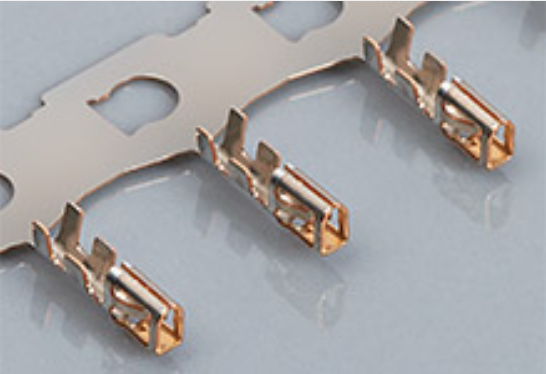 |
Part number | |
Crimper tool | |
Description | Hand crimper tool 28-32 AWG |
Image (Reference only. Please verify with supplier's datasheet) |  |
Part number | |
J1, J2, J3, J4 Crimped wires 150 mm | |
Description | Molex Pico-Clasp™ 28 AWG black jumper lead socket to socket 150 mm length. Gold plated. |
Image (Reference only. Please verify with supplier's datasheet) | 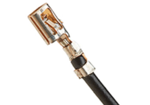 |
Part number | |
J1, J2, J3, J4 Crimped wires 300 mm | |
Description | Molex Pico-Clasp™ 28 AWG black jumper lead socket to socket 300mm length. Gold plated. |
Image (Reference only. Please verify with supplier's datasheet) | 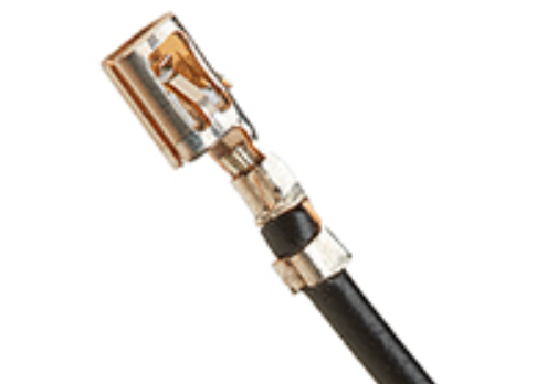 |
Part number | |
Wiring accessory: Spiral wire wrap | |
Description | Nylon spiral wrap abrasion resistant. Internal diameter: 2.41 mm, 3.18 mm expanded | 5.08 mm, 6.35 mm expanded |
Image (Reference only. Please verify with supplier's datasheet) | 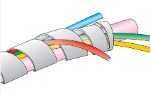 |
Part number | |
Wiring accessory: wire to wire solder sleeve | |
Description | Wire to Wire Solder Sleeve Heat shrinkable. Can be used to reliably connect pre-crimped wires to a specific sensor, feedback, or other thin wires. |
Image (Reference only. Please verify with supplier's datasheet) |  |
TE | |