Homing
Homing is a set of motion sequences used for locating the "home" position of the system. This method is usually needed:
In systems using incremental position encoders. After power on, homing is used to locate the 0 (home) position.
In systems using absolute position encoders. Usually, it is used to apply an offset to the position readings after power on to have a different 0 position than the absolute encoder one.
Homing movements are based on velocity mode with the profiler. When homing mode is enabled, user commands (target velocity) are ignored.
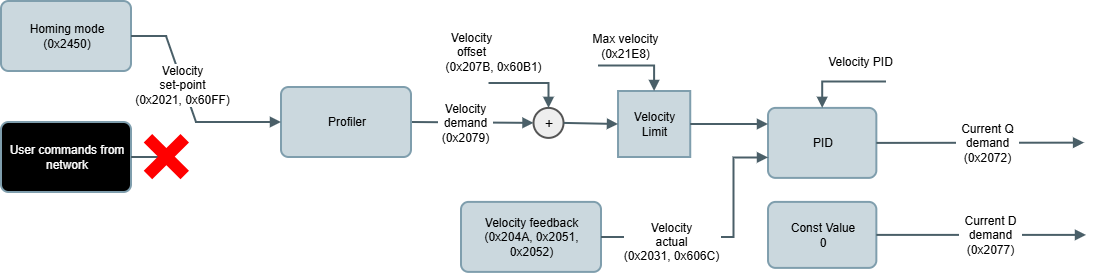
There are several homing methods to find the home position on summit drives, they are listed below. They are selected using the 0x2450 - Homing mode register.
Following parameters are related to all homing methods:
0x2451 - Homing offset/0x607C - Home offset. Sets a desired actual position value after the homing procedure has finished.
0x2452 - Homing timeout. If the whole homing process is not finished within the time specified, the homing process is aborted at this point and the status word error bit is set.
0x2010 - Control word/0x6040 - Control Word. It is used to start the homing procedure.
0x2011 - Status word/0x6041 - Status Word. Several bits of the status word register indicate the homing procedure status.
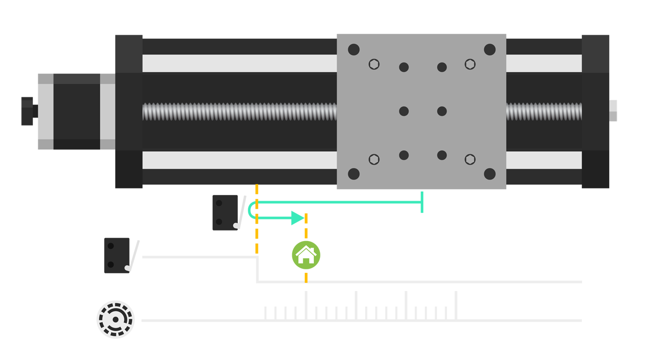
Homing on current position
Homing position is the current position.
This homing mode does not move the motor.
Furthermore, this homing can be done with the motor disabled (out of Operation Enable state).
This homing mode is almost instantaneous, so the homing procedure status (status word bits) will signal only the final homing state.
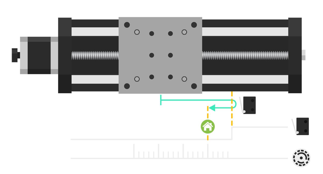
Homing on the positive limit switch
This method starts motor movement in a positive direction until a change on the output signal of an electromechanical switch placed at the rightmost position is detected.
Afterward, the axis is moved in a negative direction until the switch signal toggles its value again. This is the homing point.
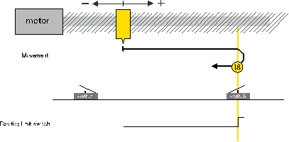

Two search speeds are used during this homing method:
0x2453 - Homing limit search speed/0x6099 - Homing speed. Speed to search for the switch or mechanical limit, which may be relatively fast.
0x2454 - Homing zero search speed/0x6099 - Homing speed. Speed to search for the actual homing point, which should be considerably slower.
Increasing homing speeds can affect the accuracy of switch detection since the device reaction time is reduced.
Limit switch source is selected setting parameter 0x2455 - Positive homing switch.
Homing on the negative limit switch
This method starts motor movement in a negative direction until a change on the output signal of an electromechanical switch placed at the leftmost position is detected.
Afterward, the axis is moved in a positive direction until the switch signal toggles its value again. This is the homing point.
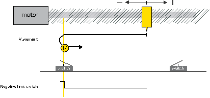
Two search speeds are used during this homing method:
0x2453 - Homing limit search speed/0x6099 - Homing speed. Speed to search for the switch or mechanical limit, which may be relatively fast.
0x2454 - Homing zero search speed/0x6099 - Homing speed. Speed to search for the actual homing point, which should be considerably slower.
Increasing homing speeds can affect the accuracy of switch detection since the device reaction time is reduced.
Limit switch source is selected setting parameter 0x2456 - Negative homing switch.
Homing on positive index pulse
This method starts motor movement in a positive direction until an index pulse is received. This is the homing point.
Used search speed is the 0x2454 - Homing zero search speed/0x6099 - Homing speed.
Increasing homing speed can affect the accuracy of index detection since the device reaction time is reduced.
Index pulse source is selected setting parameter 0x2457 - Homing index pulse source.
Homing on negative index pulse
This method starts motor movement in a negative direction until an index pulse is received. This is the homing point.
Used search speed is the 0x2454 - Homing zero search speed/0x6099 - Homing speed.
Increasing homing speed can affect the accuracy of index detection since the device reaction time is reduced.
Index pulse source is selected setting parameter 0x2457 - Homing index pulse source.
Homing on the positive limit switch and index pulse
This method starts motor movement in a positive direction until a change on the output signal of an electromechanical switch placed at the rightmost position is detected.
Afterwards, the axis is moved in a negative direction until the switch signal toggles its value again. When the switch signal has toggled, the movement continues until an index pulse is received. This is the homing point.
Two search speeds are used during this homing method:
0x2453 - Homing limit search speed/0x6099 - Homing speed. Speed to search for the switch or mechanical limit, which may be relatively fast.
0x2454 - Homing zero search speed/0x6099 - Homing speed. Speed to search for the actual homing point, which should be considerably slower.
Increasing homing speeds can affect the accuracy of switch detection since the device reaction time is reduced.
Limit switch source is selected setting parameter 0x2455 - Positive homing switch.
Index pulse source is selected setting parameter 0x2457 - Homing index pulse source.
Homing on the negative limit switch and index pulse
This method starts motor movement in a negative direction until a change on the output signal of an electromechanical switch placed at the leftmost position is detected.
Afterwards, the axis is moved in a positive direction until the switch signal toggles its value again. When the switch signal has toggled, the movement continues until an index pulse is received. This is the homing point.
Two search speeds are used during this homing method:
0x2453 - Homing limit search speed/0x6099 - Homing speed. Speed to search for the switch or mechanical limit, which may be relatively fast.
0x2454 - Homing zero search speed/0x6099 - Homing speed. Speed to search for the actual homing point, which should be considerably slower.
Increasing homing speeds can affect the accuracy of switch detection since the device reaction time is reduced.
Limit switch source is selected setting parameter 0x2456 - Negative homing switch.
Index pulse source is selected setting parameter 0x2457 - Homing index pulse source.