LED signals reference
LED signals definitions
LED state | Description |
|---|---|
On | The LED is constantly on. |
Off | The LED is constantly off. |
Flickering | The LED flickering will have an On and Off sequence with a frequency of approximately 10 Hz: on for approximately 50 ms and off for approximately 50 ms. 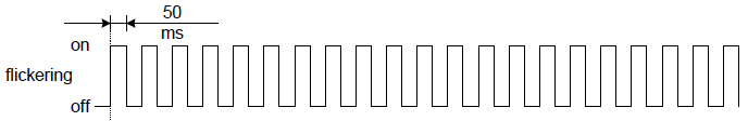 |
Blinking | The LED blinking will have an On and Off sequence with a frequency of approximately 2,5 Hz: On for approximately 200 ms followed by Off for approximately 200 ms. 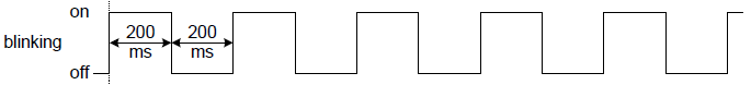 |
Single flash | The LED will have a short flash (approximately 200 ms) followed by a long off phase (approximately 1000 ms). 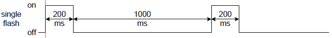 |
Double flash | The LED will have a sequence of two short flashes (approximately 200 ms), separated by an off phase (approximately 200 ms). The sequence is finished 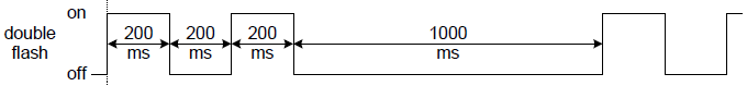 |
Triple flash | The LED will have a sequence of three short flashes (approximately 200 ms), separated by an off phase (approximately 200 ms). The sequence is finished 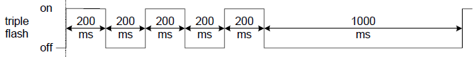 |
LED signals
LED signal | Meaning |
|---|---|
FAULT LED (Red) | Signals if the drive is in fault state. See State Machine in Operation section and Error management section for further information.
|
EtherCAT
In EtherCAT firmware, LED signals are described by the following table:
LED signal | Meaning | ||
|---|---|---|---|
RUN LED (Green) | Provides information about the EtherCAT network state machine, according to EtherCAT specification. | ||
LED State | EtherCAT slave status | ||
Off | INIT | ||
Flickering | BOOTSTRAP | ||
Blinking | PRE-OPERATIONAL | ||
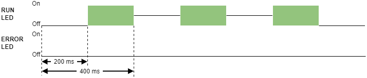
Single Flash | SAFE-OPERATIONAL | ||
On | OPERATIONAL | ||
ERROR LED (Red) | Provides information about the EtherCAT communication status, according to EtherCAT specification. | ||
LED state | EtherCAT slave status | ||
Off | No error | ||
Blinking | Invalid configuration | ||
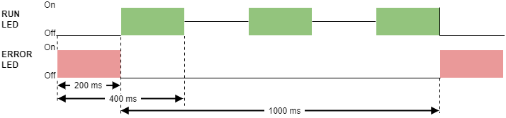
Single flash | Local error | ||
Double flash | Watchdog timeout | ||
LINK0 & LINK1 | Provide information about the Ethernet Link Status in each port. | ||
LED state | EtherCAT slave status | ||
On | Port closed | ||
On-Off alternating | Port opened (activity on port) | ||
Off | Port opened (no activity on port) | ||
CANopen
In CANopen firmware, LED signals are described by the following table:
LED signal | Meaning | ||
|---|---|---|---|
RUN LED (Green) | Provides information about the CANopen network state machine, according to CiA 303-3 specification. | ||
LED state | CANopen slave status | ||
Off | Device is switched off | ||
Blinking | PRE-OPERATIONAL | ||
Single Flash | STOPPED | ||
On | OPERATIONAL | ||
ERROR LED (Red) | Indicates the status of the CAN physical layer and errors due to missed CAN messages. | ||
LED state | Event | Description | |
Off | No error | Device is in working condition. | |
Single flash | Warning limit reached | At least one of the error counters of the CAN controller has reached or exceeded the warning level (too many error frames). | |
Double flash | Error control event | A guard event (NMT-slave or NMT-master) or a heartbeat event (heartbeat consumer) has occurred. | |
Triple flash | Sync error | The sync message has not been received within the configured communication cycle period time out. | |
On | Bus off | The CAN controller is in bus off state. | |
LINK0 & LINK1 | Provide information about the Ethernet Link Status in each port. | ||
LED state | Port state | ||
Off | Port closed | ||
On-off alternating | Port opened (activity on port) | ||
On | Port opened (no activity on port) | ||
|
In Everest (EVE) and related products, both Ethernet ports are available and they act as an Ethernet switch. In CAP, DEN, EVS and related products, only Ethernet 1 is available, so only LINK1 signal is present. | |||
LEDs at start-up & Troubleshooting
After powering on, some of the LED signals can help troubleshoot.
EtherCAT
LED signal | Expected start-up behavior |
|---|---|
LINK0 and LINK1 (Green) | ON-OFF alternating → The port is open and ready for activity. If EtherCAT cables are connected on ECAT Port 0/1, Link LEDs will light according to the definition. EtherCAT firmware starts with no other LED because the slave will stay in INIT State after power-up until an EtherCAT master forces it to transition to another state. |
RUN LED (Green) | OFF → The slave will stay in INIT State after power-up until an EtherCAT master forces it to transition to another state. |
ERROR LED (Red) | OFF → The slave will stay in INIT State after power-up until an EtherCAT master forces it to transition to another state. Then, some errors may appear causing the LED to turn ON. If RUN LED is OFF (INIT state) and ERROR LED is Blinking after an EtherCAT master state change, it may indicate that the drive is running the FoE Bootloader. |
FAULT LED (Red) | OFF → If the initialization process is correct. Otherwise, ON. |
The rest of the LED signals follow the standard behavior.
CANopen
LED signal | Start-up behavior |
|---|---|
RUN LED (Green) |
|
ERROR LED (Red) |
|
RUN & ERROR LED |
|
FAULT LED (Red) |
|
The rest of the LED signals follow the standard behavior.