Skip table of contents

Voltage mode

This mode is used to apply a voltage directly to the actuator. It requires a proper configuration of the commutation sensor.

The commutation sensor configuration process is described in the Commutation section.

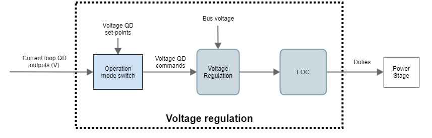
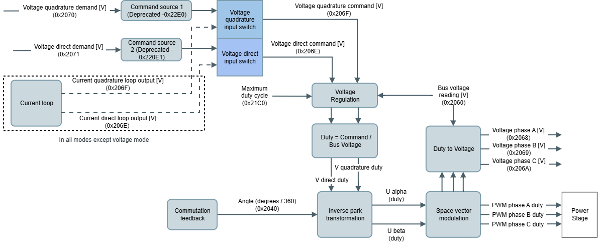
The voltage commands for the voltage module are provided in Volts and can come either from the current loop or directly from the voltage demands. Voltage demands come directly from the voltage set-points.

Inside the voltage regulation block, the voltage commands are converted to duty using the bus voltage readings at each specific time or the maximum duty cycle commanded taking the most restrictive from both.

Related registers:

  • Voltage quadrature set-point and voltage direct set-point
  • Voltage quadrature demand and voltage direct demand
  • Voltage quadrature command and voltage direct command
  • Bus voltage value contains the instantaneous bus voltage reading
  • Maximum duty cycle contains the maximum duty cycle provided
  • Voltage phase A, Voltage phase B and Voltage phase C


If software position limits are enabled using this mode of operation, the drive will generate a fault if the position limits are exceeded. Set them to 0 to disable this functionality or disable the fault generation masking it.

If actuator velocity overcomes the max. velocity parameter using this mode of operation, the drive will generate a fault. Disable the fault generation masking it.


If current measurements surpass the max. current parameter using this mode of operation, the drive will generate a fault. Disable the fault generation masking it.

In this mode, this drive is still protected by the main protections such as over/under voltage, over/under temperature, short-circuits, and I2T.

Command sources

Summit series devices allow different command sources for the different voltage references. In the voltage operation mode, the command sources are the following.

Analog inputs command source availability depends on the product.

Command source 1

Command source 1 provides the quadrature voltage reference. Three different command sources can be selected

  • Network. When command source is selected to "Network", the demand value of the loop is used as reference
  • Analog input 1. When command source is selected to "Analog input 1", the device uses the analog input 1 readings as reference. Profilers are not functional with this command source.
  • Analog input 2. When command source is selected to "Analog input 2", the device uses the analog input 2 readings as reference. Profilers are not functional with this command source.


Note

The device's analog inputs must be configured before using the Analog input command source. The configuration allows setting a Gain and offset to match the analog input range to the units of the operation mode being used.

Command source 2

Command source 2 provides the direct voltage reference. Three different command sources can be selected

  • Network. When command source is selected to "Network", the demand value of the loop is used as reference
  • Analog input 1. When command source is selected to "Analog input 1", the device uses the analog input 1 readings as reference. Profilers are not functional with this command source.
  • Analog input 2. When command source is selected to "Analog input 2", the device uses the analog input 2 readings as reference. Profilers are not functional with this command source.


Note

The device's analog inputs must be configured before using the Analog input command source. The configuration allows setting a Gain and offset to match the analog input range to the units of the operation mode being used.

JavaScript errors detected

Please note, these errors can depend on your browser setup.

If this problem persists, please contact our support.