Application Note - STO interface for multiple Summit Series NET drives
Revision History
Rev. | Date | Description | Author(s) | Reviewer(s) |
|---|---|---|---|---|
A |
| First version of the document. | Ricard Picas | Carlos Cobo |
B |
| Clarified differences between DEN-NET, EVS-NET and CAP-NET in the FMEA. | Ricard Picas | Carlos Cobo |
Scope
This document provides some examples about how to interface multiple Summit Series NET drives in a single interface board from the Functional Safety point of view (STO function).
This document provides integration examples, which are based on Novanta Functional Safety experience, but that are not assessed or audited by any certification organism. The Summit Series drives are certified as Safety-Element Out of Context. It is the responsibility of the customer to evaluate the safety of the final application.
To know the detailed Mandatory Integration Requirements, check the drive Safety Manual.
Dual-Axis Architecture
The following diagrams propose two alternative architectures for integrating two Summit Safe NET drives in a single interface board while using a single STO input. The architectures only evaluate the integration of the power supplies and the STO input signals. The diagnosis mechanisms added are required by the single drive Integration Requirements or as a consequence of the application FMEA (see section below).
The Summit Series NET drives are tolerant to 24V failures in the Logic Supply. For this reason, two different architectures are evaluated:
Dual-Axis Architecture - 48 V PSU
Dual-Axis Architecture - 24 V PSU
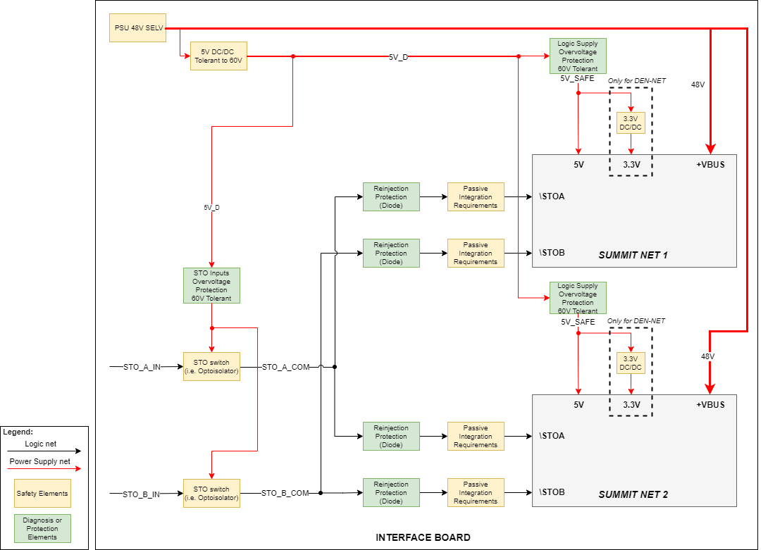
Dual-Axis Architecture - 48V PSU
The following diagram depicts an example diagram about how to implement the External Requirements circuitry for a dual-axis board supplied at 48 V. This circuit is an example and it is not space optimized.
The system includes two Summit NET axis connected to the same STO input.
The STO switch is implemented by means of Optoisolators or similar to decouple the drive from the Safety Controller
The Logic Supply is generated from a single Power Supply and it is shared between the two Summit drives.
The 5V DC/DC is tolerant to 60V input because PSU is SELV and could fail up to 60V. Using a 5V DC/DC tolerant to 60V protects the system from PSU failures.
The Logic Supply Overvoltage Protection protects the Logic Supply (5V_D for EVE-NET, CAP-NET and EVS-NET; 3.3V_D for DEN-NET) from failures in the 5V DC/DC.
An internal failure (see FMEA below) in a Summit NET drive could short the logic supplies to VBUS (48V). The faulty axis will be internally protected, but to avoid violating the second axis Integration Requirements, individual Voltage Monitors are recommended.
For the same reason, STO Inputs are overvoltage protected by means of an independent STO Inputs Overvoltage Protection. Otherwise, a failure in one axis could damage all axis STO.
The STO inputs include a Reinjection Protection, avoiding failures in one axis damaging the other axis.
An internal failure (see FMEA below) in a Summit NET drive could short the STO inputs to VBUS (48V). The faulty axis will be safe, but to avoid overriding the second axis Safety Function and violating the integration Requirements, decoupling measures (reinjection protections by means of series diodes) are recommended.
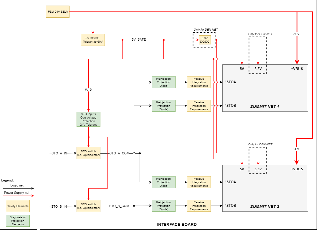
Dual-Axis Architecture - 24V PSU
The following diagram depicts an example diagram about how to implement the External Requirements circuitry for a dual-axis board supplied at 24V. This circuit is an example and it is not space optimized.
The system includes two Summit NET axis connected to the same STO input.
The STO switch is implemented by means of Optoisolators or similar to decouple the drive from the Safety Controller
The Logic Supply is generated from a single Power Supply and it is shared between the two Summit drives.
The 5V DC/DC is tolerant to 60V input because PSU is SELV and could fail up to 60V. Using a 5V DC/DC tolerant to 60V protects the system from PSU failures.
No Logic Supply Overvoltage Protection is needed, since the Summit Series NET drives are tolerant to 24V failures in the Logic Supply.
The STO inputs include a Reinjection Protection, avoiding failures in one axis damaging the other axis.
An internal failure (see FMEA below) in a Summit NET drive could short the STO inputs to VBUS (24 V). The faulty axis will be safe, but it could override the the second axis Safety Function, decoupling measures (reinjection protections by means of series diodes) are recommended.
Summit Series NET drive FMEA
The following Failure Modes and Effects Analysis (FMEA) analyses multiple failures in a Summit Series NET drive and which effects can have in the integrated application.
Potential Failure Mode | Power Supply Voltage | Potential Effect(s) on Faulty axis | Effects on Safety Function | Potential Effect(s) on Application (multiple axis) | Effects on Application Safety Function (multiple axis) | Application Mitigation Actions |
|---|---|---|---|---|---|---|
Open-circuit of STO inputs | 24 V and 48V | Safety function is activated. | SAFE | - | - | |
Open-circuit of Logic Supply
| 24 V and 48V | Safety function is activated. | SAFE | - | - | |
Open-circuit of Power Supply | 24 V and 48V | Loss of Power to the drive. No Torque possible, so Safety Function is activated. | SAFE | - | - | |
Short-circuit of Power Supply to Logic Supply | 48 V | Logic Supply net becomes connected to Power Supply. The safety function in the axis is guaranteed (no torque) in the motor. Logic Supply nets are:
| SAFE | Logic Supply net becomes connected to dangerous voltage. Integration Requirements in other axis are violated. Safety Function cannot be guaranteed. | DANGEROUS |
|
24 V | Logic Supply net becomes connected to Power Supply. The safety function in the axis is guaranteed (no torque) in the motor. Logic Supply nets are:
| SAFE | The Logic Supply function is protected against 24 V overvoltages. No violation of Integration Requirements in other axis. Safety Function activated. | SAFE | ||
Short-circuit of Power Supply to STO inputs | 24 V and 48V | STO inputs become connected to Power Supply. The safety function in the axis is guaranteed (no torque) in the motor. | SAFE | STO inputs become connected to a high-voltage. Safety function in other axis are deactivated. Integration Requirements are violated. | DANGEROUS |
|
Short-circuit between STO1 and STO2 | 24 V and 48V | Internally protected. Not feasible | SAFE | SAFE | - | |
Short-circuit between STO and Logic Supply | 24 V and 48V | Internally protected. Not feasible | SAFE | SAFE | - |


