Dimensioning a Shunt Resistor for Regenerative Braking
Online calculation tool:
Source: https://jscalc.io/calc/dtIKlDgHxyhE3FKJ
If needed this could also be used with the excel tool that can be downloaded here: http://goo.gl/jPmhm4. Note that the excel tool could not be up to date. Preferably refer to the online calculation tool.
Shunt braking resistor basics
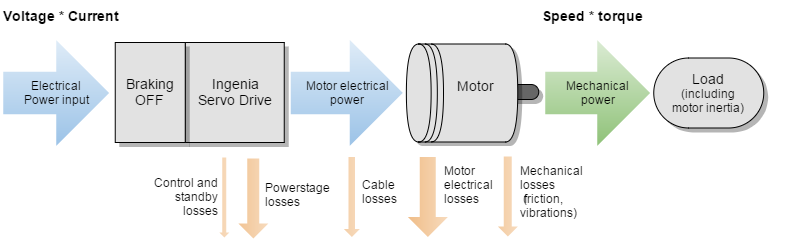
Motor power flow
During normal operation, the servo drive receives electrical power from a DC bus supply and outputs a controlled electrical power through the phases of the motor. Then the motor converts this electrical power to a mechanical power that moves the load:
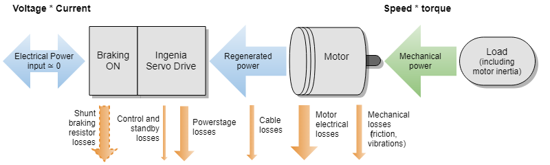
However, in regenerative mode the inertia of the load is driving the movement of the motor, not the servo drive, and thus the motor acts as a generator whose load is the servo drive and, ultimately, the DC bus supply. In the same way that the DC bus voltage is stepped-down in normal operation, the generated voltage is stepped-up in regenerative mode, which causes the DC bus voltage to increase as its capacitance is charged by the incoming current. Since this is usually a non-desired scenario, a shunt braking resistor can be connected to the servo drive to dissipate this excess of regenerated energy, preventing it to reach the DC bus.
During regenerative braking, the power stage of the servo drives operates in reverse, boosting (or stepping-up) the DC bus voltage. This means the DC bus voltage (and supply) can be higher than the value of BACK-EMF of the motor at the given speed!
In some cases, the shunt braking resistor may be avoided or minimized in the case of:
- Battery powered systems that allow recharging and have no reverse blocking diodes.
- Systems with large DC bus capacitance that can store enough braking energy.
- System that use electromagnetic brakes that dissipate the energy mechanically.
Shunt wiring
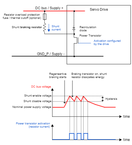
Shunt wiring of a single drive
The typical wiring circuit of a shunt resistor connected to a single servo drive is shown next. The shunt is connected between the power supply positive and the SHUNT_OUT of the drive, this is an open drain high current output. Check each product manual for detailed wiring recommendations.
An additional fuse or resettable over-current protection could be added to protect the resistor against fire or explosion in case of an unpredictable overload or a wrong configuration of the shunt activation voltage that sets the SHUNT_OUT active all the time.
Note that the fuse blowing may cause a cascade effect destroying the drive and the power supply by an over-voltage situation which may be even worse than overloading the resistor. Therefore the fuse should be designed to never blow on nominal conditions, only as a last resort to prevent fire or dangerous temperatures on the braking resistors. The fuse is not necessary:
- When using a resistor whose nominal power at working temperature exceeds Presistor > Vmax(supply)² / R. In terms of safety this is the best approach that guarantees that the shunt braking resistor will always work reliably. However it typically leads to over-sized resistors.
- When using safety resistors that are designed to fail in open-circuit fashion.
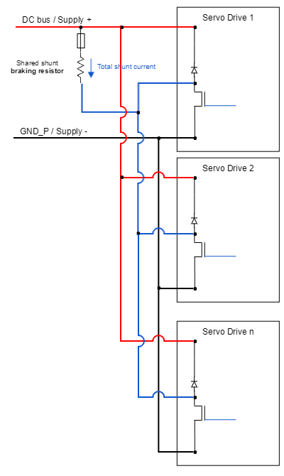
Shunt wiring of multiple drives sharing a power supply
When wiring multiple drives in parallel to the same power supply or battery, a single shunt resistor could be shared among all the axis. Do this only if the braking current of all the axes does not exceed each individual servo drive shunt current capacity.
Paralleling the shunt output is possible as the drives have an open drain output.
Quick guide for shunt braking resistor choice
Manual calculations
The following steps provide a safe, conservative approach to dimension the shunt resistor for most systems (we will consider that 100% of deceleration energy goes to the shunt resistor). In case of doubt it is better to include the shunt braking option and, if finally not needed, remove it.
- Determine your system max. kinetic energy (Ek) at max. speed and/or max. potential energy (Ep) at max. height. Calculate the mechanical energy Em:
Em = Ek + Ep
Include here motor, gearing and load inertia. For vertical loads, potential energy may be the biggest contribution. - Determine the min. deceleration time ( tdec) and max. number of decelerations per second (Db).
- Determine the resistor Ω value with the following formula:
R ≈ Vmax(supply) * 1.1 / i(shunt)
where:
Vsupply(max) (V) is the power supply max voltage including tolerances.
i(shunt) (A) is the deceleration current. If unknown, use the drive shunt current (available in the datasheets) or alternatively or if not found use drive phase peak current (from the datasheet).
Choose a standard resistor with value close to R. - Determine resistor average power Pav by:
Pav = Em * Db
Consider power-temperature derating on the resistor datasheet.
In case the duty cycle of the application is unknown, consider the highest number of deceleration cycles per second that can be physically made.
An alternative approach is to design the shunt to operate 100% of the time, in this case the power of the resistor must be Pav = Vmax(supply)² / R. This approach is conservative and may result in very big resistors but is the safest approach. - Determine the resistor peak (overload) power Ppk by the maximum of following equations
Ppk = Maximum( Em / tdec ; Vmax(supply)2 / R)
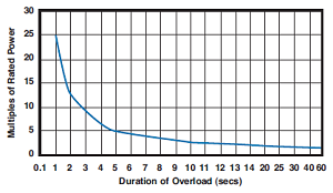
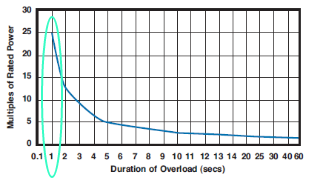
To ensure the integrity of the chosen resistor. The peak power depends on peak time, check the resistor datasheet. The Ppk (5 s) is typically:
Ppk(typ.) = Pav * 5 for wire-wound resistors. - Connect the shunt resistor according to the installation manual. Provide generous dissipation to the resistor if Pav is close to the resistor nominal power.
- Configure the servo drive shunt activation voltage. Ensure the configuration is well stored in the non volatile memory. Ensure the shunt activation voltage is always > nominal supply voltage.
Example 1/3
JUP-30/130 driver with a 30 kg vertical load on a 100 mm diameter pulley and 1 m height.Power supply is a 4.5 kW, 130 VDC with 14000 µF total capacitance (Jupiter + supply). Maximum speed is 1000 rpm.Maximum deceleration length is 6 revolutions, 1 cycle every 3 seconds.
- Calculate kinetic energy at 1000 rpm
ω0 = 104.7 rad/s
Rotor and pulley moment of inertia: 100 * 10-4 kg·m2 → Ek(rotor) = ½ * 100 * 10-4 * 104.72 = 54.8 J
Load: 1000 rpm at 100 mm diameter pulley → (1000 / 60 ) * π * 0.1 = 5.2 m/s → Ek(load) = ½ * 30 * 5.22 = 405.6 J
Ek = 54.8 + 405.6 = 460.4 J
Calculate maximum potential energy at height = 1 m
Ep = m * g * h = 30 * 9.8 * 1 = 294 J
Total mechanical energy: Em = Ek + Ep = 754.4 J - Braking time calculation (considering constant deceleration α and total angle of Θ = 6 rev = 37.7 rad):
Θ = ω0 * t + ½ * α * t2 and α = - ω0 / t → Θ = ω0 * t + ½ * (- ω0 / t ) * t2 = ω0 * t - ½ * ω0 * t = ½ ω0 · t
→ 37.7 = 0.5 * 104.7 * t → tdec = 0.72 s ; Db = 1 / 3 = 0.333 - Resistor value:
R ≈ Vmax(supply) * 1.1 / i(shunt). For Jupiter R = 130 * 1.1 / 30 = 4.7 Ω - Resistor average power:
Pav = Em * Db = 754.4 * 0.333 = 252 W - Resistor peak power:
Ppk = Em / tdec = 1047 W
Ppk ≤ Vmax(supply)2 / R → 1047 ≤ 1432 / 4.7 → 1047 ≤ 4350 W → OK!
4.7 Ω is a standard value → perfect!
Resistor part number choice
Steps for choosing the resistor part number:
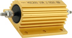
Technology: wirewound aluminium resistors are preferred due to their high peak capacity. An interesting alternative for short time overload.
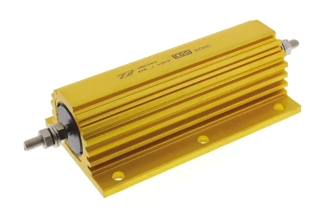
Packaging: for high power systems (> 1 kW) it is recommended to use dynamic braking resistors packs with their heatsink and housing to prevent potential burns.
.png?inst-v=9ce3183b-66f0-4f0f-b700-66dcdfc03e82)
.png?inst-v=9ce3183b-66f0-4f0f-b700-66dcdfc03e82)
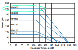
Environmental: Take into account heatsink or air temperature for the average power rating.
Power overload: For peak power use the graphs or ratings specified on the manual. Sometimes even the peak energy is specified.
Example 2/3
Choosing the resistor part number. Calculated specs are: R = 4.7 Ω, Pav ≥ 251 W, Ppk ≥ 1047 W. Filtering on Digi-Key. Seems that the best option is HSC3004R7J.
Technology: Wirewound aluminum resistor
Packaging: Compared to Ohmite alternative, it includes screws for fastening.
Environmental: Air temperature is unknown, choosing the 250 W could not be enough, 300 W is chosen.
Power overload: 25 x 300 = 7500 W → 1047 ≤ 7500 → OK!
Configuration of the shunt parameters of the drive
Ingenia driver configuration for ECORE line.
- Set max user bus voltage (i.e. shunt activation voltage) (0x2101:0x02) to the voltage you want the shunt transistor to be activated at.
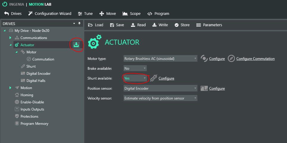
- In the actuator window, set Shunt Available to Yes and write the change to the driver.
Click on Configure and set the duty used and the hysteresis. The duty used is the duty cycle of the modulation performed in the shunt transistor and it can be changed during testing. However, it is recommended to set the value to 2048 (100%) when the engineering stage is finished.
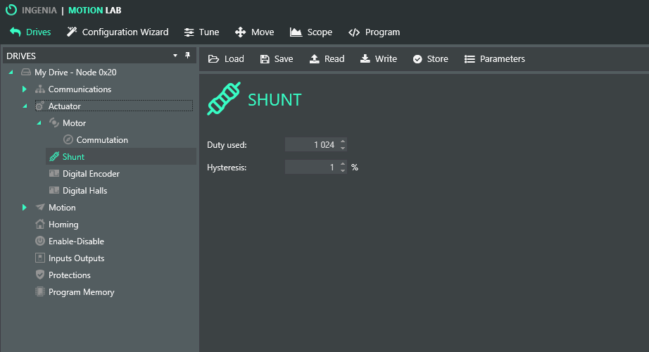
Set hysteresis (see picture below). A value of 1% is recommended.
Remember to write all the changes made to the driver.
Start testing with small accelerations and monitor DC link circuit voltage (mV) on the scope.
Some of the Ingenia drivers have an orange shunt activation LED. This should turn on during braking.

Shunt control frequencies
PWM signal for driving the shunt braking resistor is 20 kHz in most of the Ingenia Servo Drives.
DC bus voltage is sampled under a rate of 1 kHz in most of the Ingenia Servo Drives.
See more in the product manual.
Note on control loops
Control loops play an important role on the braking dynamics.
Make them less aggressive to minimise regeneration.
Minimise deceleration ramps as much as possible.
3/3 Example
For Jupiter, according to the results obtained previously:
- Select the available shunt resistor checkbox.
- Set Duty used to 2047.
- Set max user bus voltage (i.e. shunt activation voltage) (0x2101:0x02) to 130 * 1.1 = 143 V
- Set Hysteresis to 1 (1%). Shunt will turn on at 144.4 V and off at 141.6 V
- Start testing with small accelerations and monitor DC link circuit voltage (mV) on the scope.
- Monitor shunt braking resistor temperature
Extra information
Moment of inertia for various shapes
.png?inst-v=9ce3183b-66f0-4f0f-b700-66dcdfc03e82)
Moment of inertia for rotational loads can be calculated as:
I = η * M * R2
where:
- η is a form factor
- M is the system mass in kg
- R is the maximum radius of the system from your axis of rotation in m
With this, kinetic energy can be calculated as:
K = ½ * I * ω2
where:
- ω is the angular speed in rad/s
Quick worst case calculation
“I don’t want to calculate the exact moment of inertia, I just want a worst case assumption to know if I need a shunt braking resistor”
Use:
I = M * R2
Where the simplification η = 1 is applied.
Using PWM modulation for driving the shunt braking resistor
Modulate PWM might be equivalent to “changing the effective value of resistor”, but:
Increases EMI
Increases power losses
Energy that can be stored on the DC bus capacitor
Using a DC bus capacitor can be sometimes a cheap alternative to using a shunt braking resistor to avoid an uncontrolled increase of the DC bus voltage in case of re-injection. However, this method has serious disadvantages:
Large voltage swing from nominal to max is needed to be effective. Watch out the power supply Overvoltage disconnection!
Huge capacitors are needed
Capacitors are typically dimensioned for EMI rather than energy storage in low voltage DC drives

