Disambiguation on current values and naming for Ingenia Drives
Overview
This document explains and clarifies how current is measured and expressed at Ingenia documentation, tools and drives. For reference next is a simplified electrical drawing of a typical 3 phase servo drive system using sinusoidal commutation:
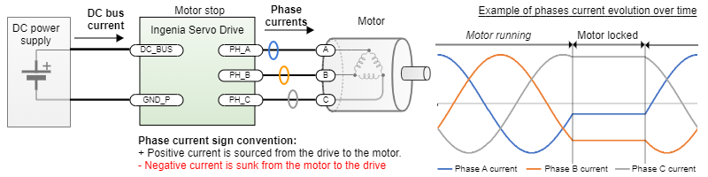
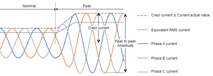
On a permanent magnet brushless motor AC that is rotating at a constant speed, the phase currents will have a sinusoidal waveform with a 120º delay between them, theoretically. For constant speed applications the current is sometimes expressed in Root Mean Square or RMS (see detailed description below). The RMS value of those currents in that situation can be calculated as Crest current / √2. For example, if your BLAC motor is rated at 17 ARMS it means the crest current will be 24 A at this rated point. However, although RMS current is commonly used in the industry for continuous power applications it does not provide a clear answer for a detailed design of many robotics applications where the frequency is not constant and the motor can be fixed on a position as can be seen in the figure. At these points, the calculation or measurement of RMS current using a typical device or multimeter could lead to non-practical results.
Because of this fact, at Ingenia manuals and documentation if not specified otherwise the current is expressed as the crest value of the phases. The software also shows either the instantaneous value for the individual phase currents or the computed "current actual value", which matches the crest positive value of the instantaneous currents. Further details on how the current is measured and controlled in Ingenia drives can be found in Current modes (CSC, C, CA).
Naming conventions
To keep the explanation free of ambiguities, consider this nomenclature:
- Instantaneous value (A): Value of the current in a specific moment in time. It is the current you would measure with an oscilloscope and a current probe on the specific motor phase.
- RMS value (ARMS): Root Mean Square current, which is computed over a period of time by making the square root of the average squares values of the instantaneous currents. This current is the equivalent DC current that would produce the same power dissipation in a resistive load. It is the current you would measure with a True RMS multimeter connected in series with the motor phases. Conversion between RMS and crest values will be presented later.
- Crest value (A): Maximum value for alternating current. It can be referred to as "peak" value, which is an ambiguous and confusing term. Note this term is sometimes referred to as "peak amplitude".
- Peak to peak amplitude (A): 2 times the crest value for a symmetrical current, corresponds to the peak to peak value of the signal.
- Nominal value (ADC or ARMS): the maximum value of continuous current that causes such power dissipation that the drive can withstand it for an infinite amount of time assuming that the environmental conditions described in the manual (ambient temperature range, presence of a heatsink, etc.) are met.
- Peak value (ADC or ARMS): the value of transient current that causes such power dissipation that the drive can withstand it for a defined peak time assuming that the environmental conditions described in the manual (ambient temperature range, presence of a heatsink, etc.) are met.
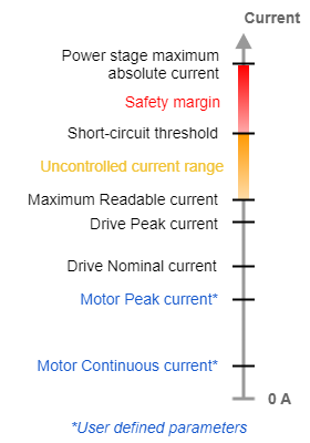
Drive currents levels description
The servo drive has several current levels or limits. Some of them correspond to registers. Summit: Current modes (CSC, C, CA).
- Current in product part number: this typically refers to the nominal crest current. Depending on the product line this criteria may change as in some drivers is specified in RMS, please always refer to the product manual for detailed current specs.
- Short-circuit threshold (A): Instantaneous current where the hardware short-circuit protections will cut the flow of current. This value shows a large tolerance, the protections are fast (typically under 1 µs) but not accurate.
Maximum Readable current (A): Maximum value of current that can be read by the Analog to Digital Converter (ADC) before it saturates.
Whenever the application maximum current < Maximum Readable current, the drive can protect the motor using i2t algorithms and control the current.
Whenever the maximum current > Maximum Readable current, the firmware will not control the current and the current waveforms may show distortion. It is not recommended to saturate the current readings.
- Drive Peak current (A): Value of the transient current that the drive can only withstand for a given Drive Peak time, under given conditions of ambient temperature and thermal dissipation. This value is expressed as crest otherwise specified. It depends on the heat capacity of the power stage and the cold plate rather than the heatsink size and area.
Drive Nominal current (A): Value of continuous current that the drive can withstand indefinitely, under given conditions of ambient temperature and thermal dissipation. Any current larger than this can trigger the drive's i2t algorithm.
- Motor Peak current (A): User-configured peak current that the motor under control can withstand for specific peak time. It is expressed as DC current. If the motor datasheet has the information in ARMS, just convert it to crest using the criteria shown next.
- Motor Rated/Nominal current (A): User-configured maximum continuous current for an specific application. Any current larger than this triggers the Motor i2t algorithm (starts integrating). This current value should never be set higher to the rated current value of the motor datasheet.
Conversion from crest current to RMS
Depending on the type of motor and/or the commutation method/mode, one of these current modes shall be met. In each case, the RMS current can be easily approximated:
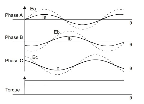
Sinusoidal modeIn sinusoidal mode, the motion controller provides phase currents with the form of a sine wave (outphased 120 degrees from each), and the 3 phases conduce current during the whole electric cycle in a way that any of them is the algebraic sum of the other 2 at all time. Therefore, the resulting torque is flat (ideally). This is accomplished by a control algorithm called Space Vector Modulation. Whenever the currents match the shape of an ideal sine, the RMS value can be calculated as: IRMS = ICREST / √2 |
|
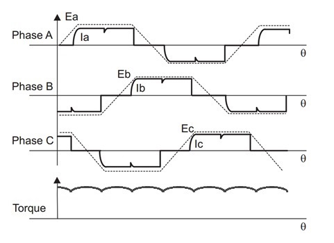
Trapezoidal modeIn trapezoidal mode, the motion controller modulates the voltage to fit the shape of a trapezoid. In this scenario, only 2 phases are active at the same time, matching the flat sections of the trapezoid, and the 3rd is left floating. Therefore, the current is positive in the phase modulated with positive voltage, it is negative in the phase modulated with negative voltage, and there is no current at all in the phase left floating, in which the observable voltage is the BEMF changing from positive to negative or vice-versa. The resulting torque shows a characteristic ripple, which is product of the fact that each 1/6th of the cycle a DC excitation is applied over a rotating magnetic field, so the resulting torque is proportional to the sine of the angle between the rotor and the excitation. As the current can be approximated to ideal square waves, the approximate RMS value of the current can be calculated as: IRMS = ICREST * √(2/3) With ICREST being the value of the current in DC during the flat section. In the diagram, the BEMF of each phase shown in dashed line. Torque and current in solid line. |
(This torque response might depend on the internal construction of the motor) |
DC modeIn DC mode, the current is simply proportional to voltage, so the controller must only modulate voltage in accordance with the required torque and direction. The RMS value of the current can be calculated as: IRMS = IDC In the diagram, voltage of each phase shown in dashed line and current in solid line. | 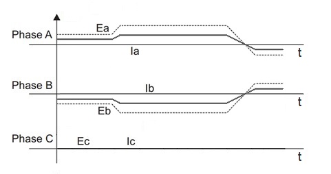 |
The Ingenia Standard for specifications and current tests
In order to standardise the tests in a measurable and reproducible way that is consistent with motion control applications Ingenia calculates:
- Drive power losses.
- Continuous and peak ratings of the drives.
- Environmental testing.
Considering the following standardised operating conditions:
- Commutation is sinusoidal with the angle fixed at 120º (phase B is maximum positive). No electrical rotation.
- Phase B sources the test current I, as the crest. For example, if the test is specified at 30 A, phase B will be sourcing 30 A continuous to the load.
- Phase A and C sink I/2 negative. Example, phase A and C current are both -15 A.
- Current is specified as the average in this "fixed crest point". Some ripple may be present but tests will be typically performed with loads whose inductance ensures a ripple of < 5% of the crest value.
This standard represents a worst-case scenario in terms of self-heating and power losses, as in a continuous rotation scenario temperatures of the 3 phases would be even. However, the stuck rotor scenario allows simpler, more qualitative measurements due to averaging, and not including extra variables such as back-EMF, frequency, speed or phase delays. It also allows using easy-to-set 3 phase RL loads.
Note, this standard may not be shared in drives previous to 2019. Always refer to the manual and reference guides.