Dynamic Braking Implementation Guide for Compatibility with STO
This guide is intended to assist clients in designing dynamic braking into their own interface boards while ensuring compatibility with Safe Torque Off (STO) functionality.
The STO function, by definition, disables the internal power stage, which means dynamic braking is not possible through the drive itself when STO is active. If dynamic braking torque is required during or immediately after STO activation, an external dynamic braking circuit must be implemented.
This document outlines how to design such a circuit, including a circuit example, integration considerations, and hardware recommendations.
Keep in mind that in the event of a failure in this circuit, the Safe Torque function must not be affected.
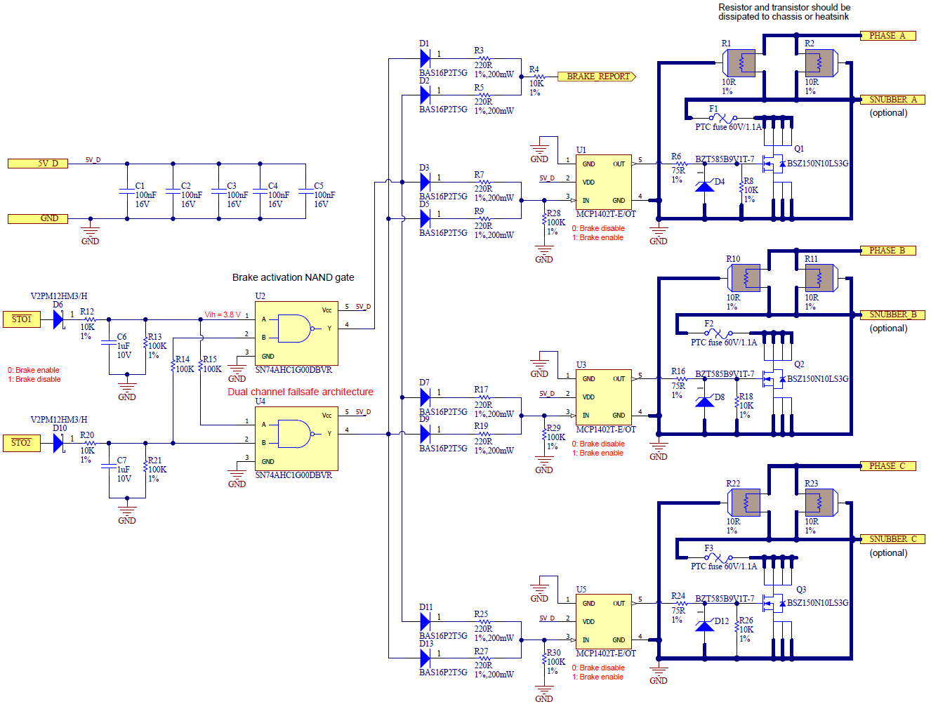
The design example implements a dynamic brake short-circuiting the phases to the ground through a 5 Ω resistor with very low height components. The activation of the brake is controlled by 2 active low enable inputs (the STO signals). In case of any of the STO signals goes low, the transistors are activated and the motor phases are shorted to ground through the resistors, effectively braking the motor in the Safe Torque Off state.
The circuit is designed to be used in a 48 V system with a max pulse power of 600 W.
Disclaimer: This guide is a reference only. It includes a schematic example and general recommendations. It is the client’s responsibility to validate the design for their specific application. Improper implementation may result in damage to the motor or drive components.
Circuit diagram example
Signals description
Signal | Description |
|---|---|
\STO1, \STO2 | Safe torque off signals. Active low. |
PHASE_A, PHASE_B, PHASE_C | Motor phases. |
SNUBBER_A, SNUBBER_B, SNUBBER_C | A capacitor could be added in this position to take advantage of the resistor and create an RC snubber, reducing the EMIs of the phases. The capacitor should be carefully selected to avoid creating resonances. |
BRAKE_REPORT | This signal reports if the dynamic braking is being activated (HIGH) or not (LOW). |
5V_D | +5 V Logic supply. |
GND | Logic supply reference voltage (GND_D). |
Design notes
To achieve maximum braking capacity and performance, transistors and resistors must be properly dissipated to chassis or heatsink.
Use a dual channel architecture to increase the robustness and maintain the functionality if one channel fails.
A delay must be added in the path to ensure that the dynamic braking is activated after the STO has been effective (the phases are not commutating) to avoid creating a short between the bus voltage and ground. In the example, this is done mainly with the resistors and capacitors at the input.
Diodes are used to protect the STO signals from failures in the dynamic braking circuitry. The diodes are duplicated to maintain the protection in case one of the diodes fails.
A resettable fuse can be used to protect the components from possible short circuits from the bus voltage to GND and overcurrents in general.
Resistors in series with the MOSFETS (5 Ω in the example) can be added to limit the current. Note that this will also limit the dynamic braking torque. Lower power resistors can also be considered, depending on the application.
Extra capacitors to GND can be added to create an RC snubber circuit and reduce EMIs in the phases. The capacitor should be carefully selected to avoid creating resonances.
Bill of Materials
Designator | Part Number | Manufacturer | Package | Value / Description |
|---|---|---|---|---|
C1, C2, C3, C4, C5 | CL05B104KO5VPNC | Samsung Electro-Mechanics | C_0402 | Ceramic capacitor 100nF 16V X7R |
C6, C7 | C1005X7S1A105K050BC | TDK Corporation | C_0402 | Ceramic capacitor 1uF 10V X7S |
D1, D2, D3, D5, D7, D9, D11, D13 | BAS16P2T5G | ON Semiconductor | SOD-923 | Diode High Speed 100V 200mA |
D4, D8, D12 | BZT585B9V1T-7 | Diodes Incorporated | SOD-523 | Diode Zener 9.1V, 0.35 W, 2% |
D6, D10 | V2PM12HM3/H | Vishay | MICROSMP | DIODE SCHOTTKY 120V 2A |
F1, F2, F3 | 2920L110/60MR | Littelfuse | 2920 | PTC fuse 60V 1.1 A |
Q1, Q2, Q3 | BSZ150N10LS3 G | Infineon | 8-PowerTDFN/TSDSON-8 | MOSFET N-CH 100V 40A 15 mΩ |
R1, R2, R10, R11, R22, R23 | RTO050C10R00FTE1 | Vishay | TO-220 | Resistor 10 Ω 1% 50W Thick Film SMD |
R3, R5, R7, R9, R17, R19, R25, R27 | ERJ-PA2F2200X | Panasonic Electronic Components | R_0402 | Resistor 220 Ω 200 mW high power pulse withstanding |
R4, R8, R12, R18, R20, R26 | RMCF0402FT10K0 | Stackpole Electronics | R_0402 | Resistor 10 kΩ 1/16 W 1 % |
R6, R16, R24 | AC0603FR-0775RL | Yageo | R_0603 | Resistor 75 Ω 100 mW 1 % |
R13, R21, R28, R29, R30 | ERJ-2RKF4702X | Panasonic Electronic Components | R_0402 | Resistor 47 kΩ 1/16 W 1 % |
R14, R15 | ASC0402-100KFT10 | Welwyn | R_0603 | Resistor 100 kΩ 1/16 W 1 % |
U1, U3, U5 | MCP1402T-E/OT | Microchip | SOT23-5N | 0.5 A MOSFET driver |
U2, U4 | SN74AHC1G00DBVR | Texas Instruments | SOT-23-5 | IC LOGIC, Positive NAND Single 2 inputs, Schmitt Trigger |
Warnings and Limitations
Consider application-specific factors such as load inertia, braking duration, and thermal limits.
Continuous dynamic braking can lead to overheating of the motor windings and braking components.
This method is intended for short-duration emergency stops or controlled deceleration, not for continuous operation.
Always verify that the braking torque is sufficient for your application without exceeding component ratings.
Disabling the power stage while dynamic braking is enabled and the motor is in motion may result in destructive operation due to high current induced in the transistors and motor.
Dynamic braking is designed to prioritize safe deceleration of the system in fault conditions. For this reason, overcurrent protections are not effective during dynamic braking, as fault conditions themselves trigger the dynamic braking. While it helps limit uncontrolled motion, it may result in component damage if current limits are exceeded. In such cases, drive or motor failure may occur as a trade-off to ensure braking safety.
The limits that could cause transistor failure during dynamic braking are the maximum continuous and peak phase current ratings specified in the product manual, and the derating should be taken into account for the safe limits.
Additionally, the motor's own current limits should be respected. If the motor's allowable phase current is lower than the transistor limits, exceeding the motor's ratings may result in motor damage, even if the transistors remain within safe operating conditions.