Motor inductance effects on servo drives
Scope
Motor inductance, or more appropriately "electrical time constant", value affects the servo drives in many ways. While high inductance values may limit the system bandwidth, low inductance values can lead to control loop instabilities, inaccuracies in current readings, increased power losses, and other problems.
This page highlights the principal effects of high and low motor inductance values on the whole servo drive system, and provides a calculator to show if a motor can be controlled by an Ingenia Servo Drive.
Online calculator
The main parameters involved in the calculation of the minimum motor electrical time constant (τe) are:
Power stage switching frequency (PWM), fPWM ;
Operating DC bus voltage, VDC ;
No load current of the motor, Ino load.
The following equations (developed and justified in the next section) summarize the criteria used to determine if a motor can be controlled by an Ingenia Servo Drive:
The following calculator helps you to check if your motor will be controllable by the driver.
Understanding the effects of low inductance motors
Simplified electrical model
The electrical circuit of a three-phase brushless electric motor (BLAC) can be modelled as follows:
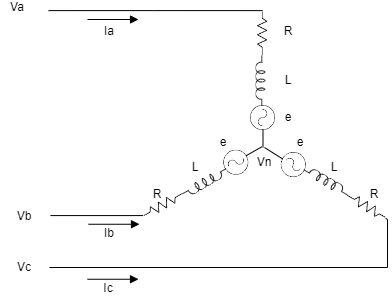
where
va, vb and vc are the phase voltages;
ia, ib and ic are the phase currents;
vn is the neutral or common-mode voltage;
R is the phase resistance, caused by the the copper wire used to create the windings;
L is the phase inductance, caused by the magnetic circuit formed by the primary and secondary circuit and is greatly affected by winding and core construction;
e is the BEMF (Back Electromotive Force) voltage generated by the magnetic field of the rotor, calculated as e = Ke • ω (where Ke is the motor electric constant and ω is the motor speed) . This voltage is proportional to the velocity and varies with slower dynamics than the motor current. For this reason, it can be compensated by the current loop and can be neglected in the following calculations.
Note that not all motor manufacturers define the L and R in the same way. Some manufacturers provide the phase resistance (R) while others provide the phase-to-phase resistance (Rph-ph = 2 x R)
For some rotor construction (salient-pole motors) the inductance is not constant, and varies with the rotor position. In that case, two different values in the d-q modelling frame are provided, Ld and Lq.
To guarantee a proper controllability, use the smaller inductance (Ld or Lq) for the calculations.
Considering this simplified model, the following three-phase equations can be obtained:
Current ripple
Since a Servo Drive uses a switching power stage, the motor currents are not constant, but include a high-frequency ripple. Ingenia Servo Drives switch the power stage at a high frequency to reduce the current ripple, but for very low inductance motors this ripple can be significant.
To simplify the calculations, consider the commutation angle where Va is maximum and Vb and Vc are equal and minimum. Consider also that motor speed and BEMF are zero. At that situation, the electrical model can be simplified as a single-phase model:
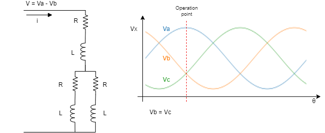
where:
v(t) is the motor applied voltage , calculated as va - vb (generated by the driver)
L is the phase inductance of the motor (H)
di/dt is the rate of change of the current (A/s)
R is the phase resistance of the motor (Ω)
i(t) is the current through the motor (A)
The current variation with time can be expressed:
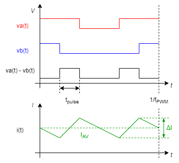
Knowing that the voltage applied is a switched waveform of amplitude DC-bus voltage and time proportional to duty cycle, the equation can be expressed as:
where:
t is the phase-to-phase pulse time;
and VDC is the DC-bus voltage.
If we consider that the initial current is zero, the current ripple Δi can be expressed as:
Note that the current ripple has twice the frequency of the switching PWM, since the voltage is applied between two phases with the PWM centered in the low-side:
Knowing that the Ingenia Servo drive uses a SVM modulation, the ripple can be calculated as follows:
where
m is ratio of voltage command (commanded voltage over VDC);
and fPWM is the switching frequency.
As can be deduced from the previous equations, current ripple is related to the motor inductance and resistance. Therefore, it can be said that, the ripple increases as lower is the electrical time constant of the motor
Limits of low inductance motors
Wrong current reading
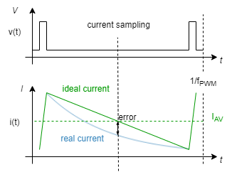
One of the main drawbacks of a very low inductance motor with a high current ripple, is that it can cause a wrong measure of the motor current. If the current sampling is not performed at the center of the ripple, the current measure could differ from the motor average current, which is providing the effective rotating torque.
The current sensing in an Ingenia Servo Drive is performed synchronously with PWM frequency, at the center of the period. Considering that the current ripple can be approximated to a triangular, the measure at the center of the pulse guarantees that the drive measures the motor average current. However, if the motor time constant is too fast, the signal can no longer be approximated to a triangular, and a wrong measure could be acquired.
As an approximation, we consider that the minimum motor time constant that allows an acceptable current measurement is the one that causes a 10% of current measurement error when controlling the motor with the minimum possible duty cycle (worst case). This can be approximated as:
Current Loop Stability
Another drawback of a very low inductance motor is the stability of the control loops. Although Ingenia Servo Drive offer high-frequency current control loops (up to 50 kHz), some motors could be impossible to control.
As a rule of thumb, the time constant of a motor cannot be smaller than the control loop sampling time:
The loop frequency (floop) varies with the power stage switching frequency. Its relation can be found on the Product Manual / Product Description page.
PWM Discretization
Another issue with the fast time constant motors is that current grows very fast. Therefore, for the minimum PWM increment that can be applied, the current rise could be significant.
The minimum PWM discretization that can be applied by an Ingenia Servo Drive is of 10 ns. Although the PWM frequency can reach up to 200 kHz, its update rate is related to the current loop frequency (maximum 50 kHz). Also, note that the current loop corrective action includes one delay cycle (zero-order hold effect). Therefore, the minimum activation time can be calculated as follows:
where
TPWMmin is the minimum PWM discretization, defined as 10 ns in Ingenia Summit Servo Drives.
From the minimum discretization time, the current raise of the motor can be calculated:
If the minimum current step between loop samples is higher than the no load current, the motor will start moving without control:
Torque ripple
Due to the current ripple, a torque ripple at PWM frequency can be expected. While the mechanical system can filter this ripple, this torque at PWM frequency can be critical in high precision positioning systems.
Magnetic core saturation and parasitic effects can also deteriorate torque performance having high current ripple.
Power loses
The motor and Servo Drive loses depend on the current flowing through the motor. High current ripple leads to high RMS current while not increasing the effective torque.
where
Electromagnetic interference
High ripple means higher conducted and radiated Electromagnetic Interferences. Motor cables will generate greater EMI with big current ripple. Conducted EMI via supply cables will also depend on inductor current to minimize that, large bulk capacitors may be needed in the DC bus.
Working with low inductance motors: tips and tricks
Reduce the power supply voltage
Minimizing supply voltage whenever possible will reduce current ripple proportionally and allow a driver to work with lower inductance values.
This is a first easy measure to reduce current ripple, electromagnetic interference and switching losses, however it may not be applicable in some cases since the maximum motor velocity will be limited by the back EMF.
Change the PWM frequency of your driver
Ingenia Servo Drives offer multiple working PWM frequencies (up to 4 values). Use the highest possible PWM frequency available in your driver.
Use the Velocity control loop
Some issues in the precise control of current can be reduced by using the velocity loop. By controlling the drive in velocity mode, the fluctuations in the current can be absorbed by a higher level controller, which closes the loop with a slower dynamic variable.
Increase the mechanical friction or test your motor with load
Very high speed motors with very low friction and fast dynamics can be difficult to control. This lack of controllability is sometimes blamed to be consequence of the low inductance, but on the contrary, is usually caused by the mechanical dynamics and velocity control loop. For this reason, it is recommended to tune and adjust the motor with the real load, which would be slower and easier to control than the motor without load.
Add external inductances in series with the motor phases
As a last solution, inductances can be added in series with each motor phase, increasing the motor time constant and reducing the ripple issues.