Understanding why the motor phase current is different than the power supply current
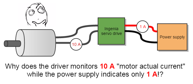
The motor current is lower than the dc current because the servo drive behaves as a step down DC/DC converter. Ignoring inefficiencies, commutation and commutation details (see below), the product of "input voltage x input current" should be equal to the "output current x effective motor voltage".
Understanding the physics
The electrical point of view
To understand why the current of the power supply is different from the motor phase current first, it is necessary to understand how an H bridge controlling a motor (inductive load) works.
As an example, it is going to be supposed the use of a DC brushed motor. Suppose also the use of 2 quadrants switching scheme, as seen in the next figure:
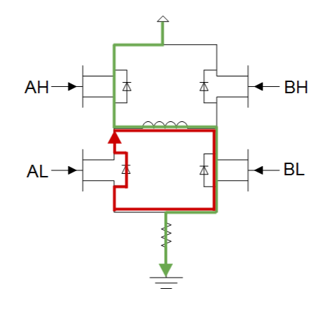
Now, let's analyze what happens when switching. The BL transistor is always at 1 state, so it could be modeled as a short circuit. The BH is always at 0 state, so it could be modeled as an open circuit. The AL transistor is always at 0 state, but its diode is used as a current recirculation way, so the transistor can be eliminated and can model it as a single diode. The AH is the switching transistor, so it's internal diode can be eliminated and can be modeled as a single transistor. Having into account the normal model of a motor, the resulting scheme is shown in the next figure.
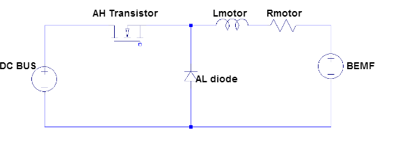
As can be seen, the model of the motor and it's switching grid can be simplified to a DC/DC Buck converter. It can be done, with little variations, in a 3 phase grid, and with any switching scheme.
Analyzing the model
To understand why the current of the motor can be superior to the input consumption only is necessary to apply the basic DC/DC converter principles.
The current flowing through a buck converter can be divided in two parts during a switching period, the current when the transistor is active (duty), and when the transistor is not active (1-duty). The next figures show the current flowing in both cases.
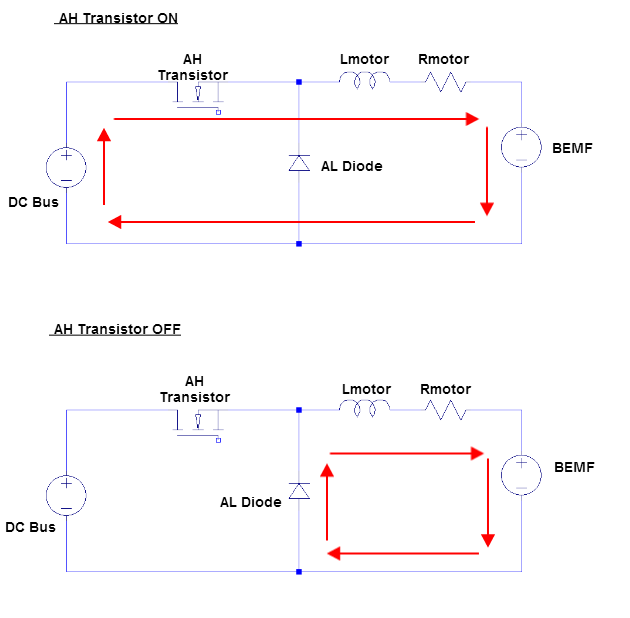
As can be seen, the current flows always through the motor, but not through the DC Bus. As a motor is an inductive charge and the current through an inductor never can change suddenly its value, when AL transistor switches to OFF, the current recirculate through the diode. The current through an inductance is defined by the next formula:
The waveform of the voltage and the current during a switching cycle, supposing steady-state and continuous conduction mode (which is the normal operation), is shown in the next figure.
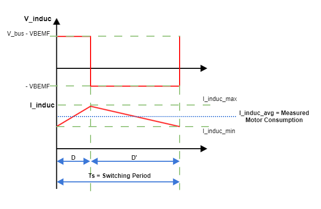
As can be seen, in the TON, the inductance stores energy due to a positive voltage over it, so it's current rises. In the TOFF the current falls due to a negative voltage (-BEMF if we ignore the resistance of the motor) and so on, the inductance loses energy (transferred to the motor and converted to movement, heating, etc). When measuring the current, the measured value will be the average value of this current ripple.
Now, let's see why the input current can be different from the output current. As mentioned before, the current flows always through the inductor, but only in TON flows through the AH transistor, this means that the average current through them is not equal, and the average value of those current corresponds to the RMS or DC value of these currents. The next figure shows it graphically.
![]()
The energy conservation point of view
Another way to understand this conversion is seeing the switching grid and the inductor as a "black box" which simply stores energy during TON and drops it during TOFF and on average, energy es conserved. If power losses are neglected:
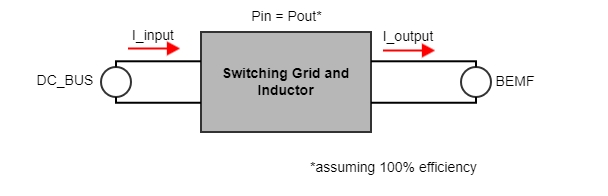
In the previous figure, the input voltage, the BEMF, and the output current are fixed values. As Pin=Pout must be equal (inductor cannot stores energy forever and the steady-state must be reached), the input current value will follow the next formula:
So, if the voltage of the BEMF is lower than the DC voltage, then the value of the DC current will be lower than the motor current because the power balance must be maintained. If the motor speed is high, the back electromagnetic force voltage (BEMF) will increase. For a given current, the PWM duty cycle will be higher. This means that motor current ~ power supply at maximum motor speed (maximum PWM duty cycle).
Conclusions
- The power stage behaves as a step-down switching converter. The motor effective voltage generated by the driver is always equal to or lower than the DC bus voltage.
- Therefore, to keep the power of input and output balanced, the output - motor - current should be higher than the input.
- This gets complicated with PMAC or brushless but the principles are similar to a brushed DC.
- At low speeds the difference between motor and DC bus current is big.
- At the highest motor speed (∝ high BEMF), the motor current and power supply current will be similar.
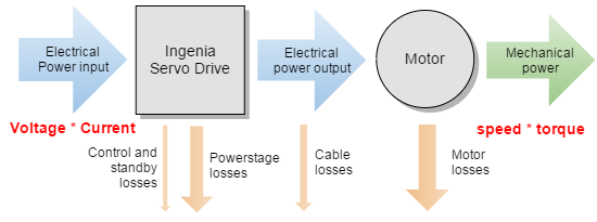
This can be understood also from the power balance point of view. Motor mechanical power is speed * torque while input power is voltage * current.
At low speeds net mechanical power is ~ 0, therefore most of the energy is basically converted into losses. Only when the speed increases, net power increases.
Energy conservation principle is not violated 😛
No, our drivers do not provide free infinite free energy. If you calculate electrical power entering the driver and exiting the driver the balance is Pin = Pout + Ploses.