0x2011 - Status word
Index | Sub Index | Name | Data Type | Acc. | Pdo Map. | NVM | Value range | Default value | Units |
|---|---|---|---|---|---|---|---|---|---|
0x2011 | 0x00 | Status word | UINT16 | RO | Yes | No | Data type | 0 | - |
This register allows knowing the drive status.
The binary representation of the status word value and its corresponding meaning is as follows:
Bit number | 15 | 14 | 13 | 12 | 11 | 10 | 8 .. 9 | 7 | 6 | 5 | 4 | 3 | 2 | 1 | 0 |
|---|---|---|---|---|---|---|---|---|---|---|---|---|---|---|---|
User bit | Commutation feedback aligned | Operation mode specific | Switch limits active | Target reached | Reserved | Warning | Switch on disabled | Quick stop | Voltage enabled | Fault | Operation enabled | Switched on | Ready to switch on | ||
State machine dedicated bits
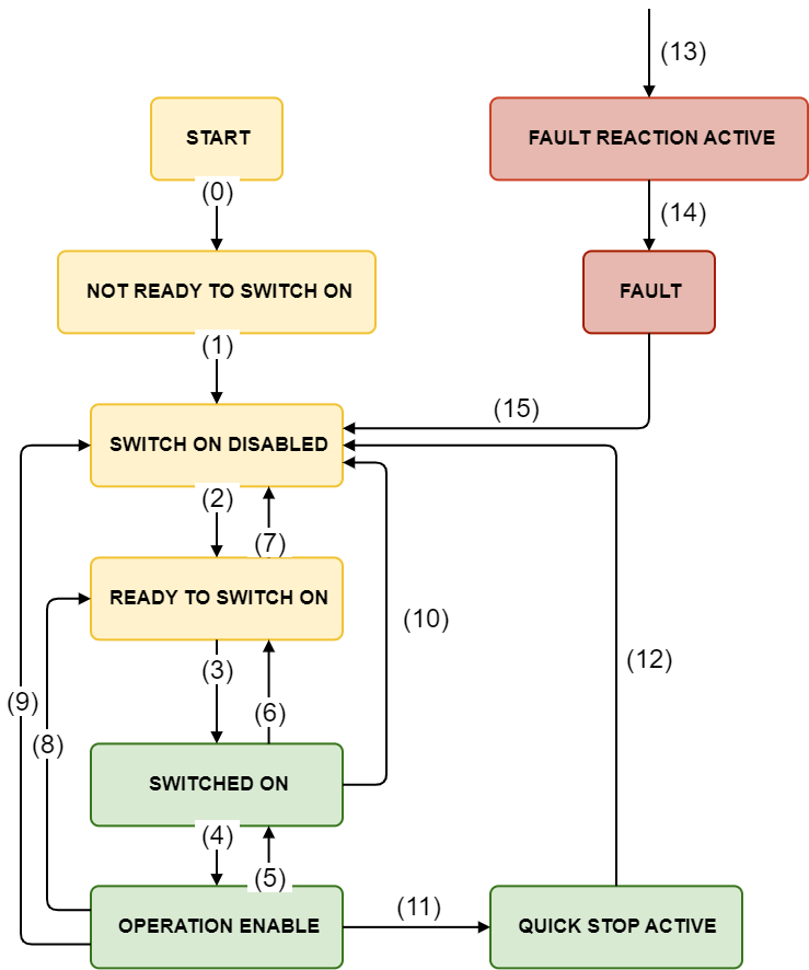
Bits 0-3, 5 and 6 determine the drive state:
Value (binary) | Status |
|---|---|
xxxx xxxx x0xx 0000 | Not ready to switch on |
xxxx xxxx x1xx 0000 | Switch on disabled |
xxxx xxxx x01x 0001 | Ready to switch on |
xxxx xxxx x01x 0011 | Switched on |
xxxx xxxx x01x 0111 | Operation enabled |
xxxx xxxx x00x 0111 | Quick stop active |
xxxx xxxx x0xx 1111 | Fault reaction active |
xxxx xxxx x0xx 1000 | Fault |
Note that the Quick stop bit is activated at a low level.
Switch limits active bit
Bit 11 indicates if an internal drive limitation in motion is being applied. This limit implies that the drive is taking control of the motor in, for example, limiting movements in one direction when a switch limit is pressed.
Commutation feedback aligned bit
Bit 14 contains the information of the commutation alignment state. After power on this bit is 0 as the commutation feedback is not aligned. The first time the drive enters in operation enabled state, a phasing procedure is started (forced or non-forced) and this bit is set once is finished successfully. This bit is reset every time a feedback is modified.
User bit
Bit 15 contains a bit that can be configured to indicate different events of the drive.
This bit is not supported on all the drives and firmware versions. Drives supporting this bit by default contains the halt command information.
Specific mode bits
The status word includes 2 mode-specific bits (bits 12 and 13) that change their meaning depending on the mode of operation.
Status word in homing mode
The binary representation of the object value and its corresponding meaning is as follows:
Bit number | 15 | 14 | 13 | 12 | 11 | 10 | 9 | .. | 0 |
|---|---|---|---|---|---|---|---|---|---|
- | Homing error | Homing attained | - | Target reached | - | ||||
The meaning of each bit is described below, depending on its value:
Homing error | Homing attained | Target reached | Description |
|---|---|---|---|
0 | 0 | 0 | Homing procedure is in progress |
0 | 0 | 1 | Homing procedure is interrupted or not started |
0 | 1 | 0 | Homing is attained but target is not reached |
0 | 1 | 1 | Homing mode carried out successfully |
1 | 0 | 0 | Homing error occurred; |
1 | 0 | 1 | Homing error occurred; |
1 | 1 | x | Reserved |
Status word in profile velocity mode
Bit number | 15 | 14 | 13 | 12 | 11 | 10 | 9 | .. | 0 |
|---|---|---|---|---|---|---|---|---|---|
- | Following error | Speed | - | Target reached | - | ||||
The meaning of each bit is described below, depending on its value:
Name | Value | Description |
|---|---|---|
Target reached | 0 | Target velocity / position not reached |
1 | Target velocity /position reached | |
Speed | 0 | Speed is not zero |
1 | Speed is zero | |
Following error | 0 | No following error |
1 | Following error |
Speed bit requires velocity threshold and velocity threshold time configured
Target reached bit requires velocity window and velocity window time configured
Status word in profile position mode
The binary representation of the register value and its corresponding meaning is as follows:
Bit number: | 15 | 14 | 13 | 12 | 11 | 10 | 9 | … | 0 |
|---|---|---|---|---|---|---|---|---|---|
- | Following error | Set-point ack. | - | Target reached | - | ||||
The meaning of each bit is described below, depending on its value:
Name | Value | Description |
|---|---|---|
Target reached | 0 | Target position not reached |
1 | Target position reached | |
Set-point acknowledge | 0 | Trajectory generator has not assumed the positioning values |
1 | Trajectory generator has assumed the positioning values | |
Following error | 0 | No following error |
1 | Following error |
Target reached bit in position modes needs position window and window time configured to be able to use this feature.
Status word in cyclic synchronous torque, cyclic synchronous velocity, and cyclic synchronous position modes
The binary representation of the register value and its corresponding meaning is as follows:
Bit number: | 15 | 14 | 13 | 12 | 11 | 10 | 9 | … | 0 |
|---|---|---|---|---|---|---|---|---|---|
- | Following error | Drive follows the command value | - | - | - | ||||
The meaning of each bit is described below, depending on its value:
Name | Value | Description |
|---|---|---|
Drive follows the command value | 0 | The drive does not follow the target value |
1 | The drive follows the target value | |
Following error | 0 | No following error |
1 | Following error |
Status word in other position and velocity modes
Bit number | 15 | 14 | 13 | 12 | 11 | 10 | 9 | .. | 0 |
|---|---|---|---|---|---|---|---|---|---|
- | Following error | - | - | Target reached | - | ||||
The meaning of each bit is described below, depending on its value:
Name | Value | Description |
|---|---|---|
Target reached | 0 | Target velocity / position not reached |
1 | Target velocity /position reached | |
Following error | 0 | No following error |
1 | Following error |
Target reached bit requires velocity / position window and window time configured