0x6040 - Control Word
Index | Sub Index | Name | Data Type | Acc. | Pdo Map. | NVM | Value range | Default value | Units |
|---|---|---|---|---|---|---|---|---|---|
0x6040 | 0x00 | Control Word | UINT16 | RW | Yes | No | UINT16 | 0x0000 | - |
The control word register allows operating the drive state machine and several modules.
Data description
The binary representation of the control word value and its corresponding meaning is as follows:
| Bit number | 15 | … | 11 | 10 | 9 | 8 | 7 | 6 | 5 | 4 | 3 | 2 | 1 | 0 |
|---|---|---|---|---|---|---|---|---|---|---|---|---|---|---|
| Manuf. specific | Reserved | Mode specific | Halt | Fault reset | Mode specific | Enable operation | Quick stop | Enable voltage | Switch on | |||||
State machine dedicated bits
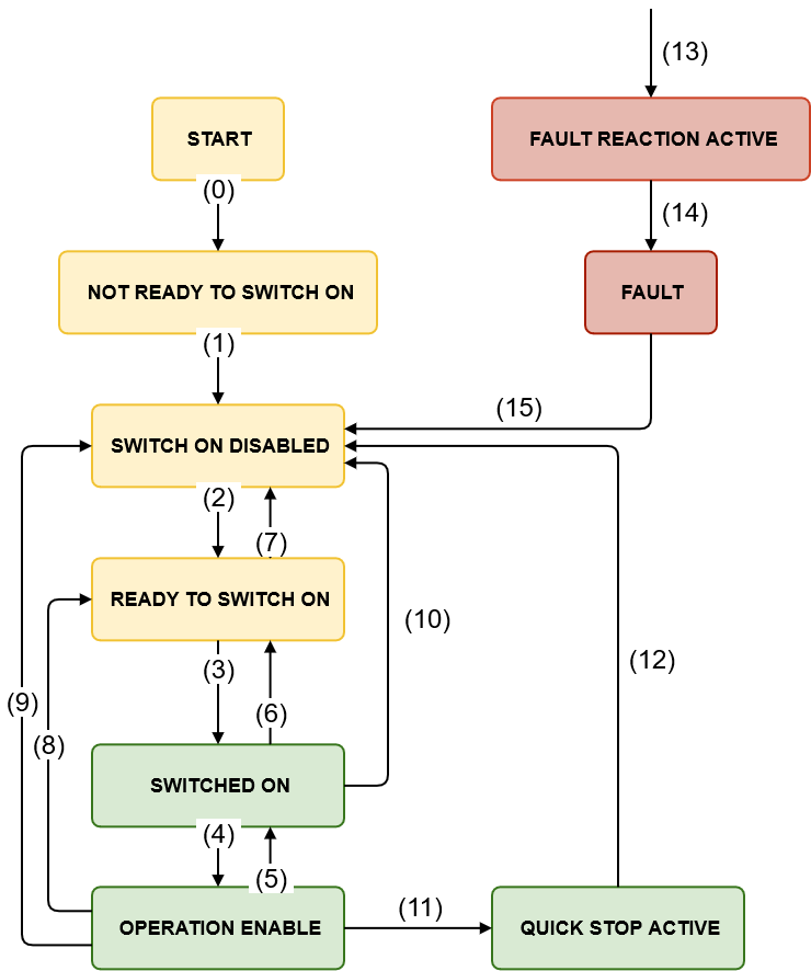
Device control commands are generated by a combination of control word bits.
Command patterns are shown below:
Command | Bit of the control word | |||||
|---|---|---|---|---|---|---|
Fault reset | Enable operation | Quick stop | Enable voltage | Switch on | Typical control word value (decimal) | |
Shutdown | 0 | X | 1 | 1 | 0 | 6 |
Switch on | 0 | 0 | 1 | 1 | 1 | 7 |
Switch on + | 0 | 1 | 1 | 1 | 1 | 15 |
Disable voltage | 0 | X | X | 0 | X | 0 |
Quick stop | 0 | X | 0 | 1 | X | 2 or 11 |
Disable operation | 0 | 0 | 1 | 1 | 1 | 7 |
Enable operation | 0 | 1 | 1 | 1 | 1 | 15 |
Fault reset | 0 to 1 (rising edge) | X | X | X | X | 128 |
Bits marked with an "X" are irrelevant.
The controller supports the following events and actions.
Transition | Event | Action |
|---|---|---|
0 | Automatic transition after power-on or reset application. | Drive device self-test and/or self initialization is performed. |
1 | Automatic transition after initialization. | Communications are activated. |
2 | Shutdown command received. | None. |
3 | Switch on command received. | The high-level power is switched on. |
4 | Enable operation command received. | The drive function is enabled. |
5 | Disable operation command received. | The drive function is disabled. |
6 | Shutdown command received. | The high-level power is switched off. |
7 | Quick stop or disable voltage command received. | None. |
8 | Shutdown command received. | The drive function is disabled, and the high-level power is switched off. |
9 | Disable voltage command received. | The drive function is disabled, and the high-level power is switched off. |
10 | Disable voltage or quick stop command received. | The high-level power is switched off. |
11 | Quick stop command received. | The quick stop function is started. |
12 | Automatic transition when the quick stop function is completed or disable voltage command is received from control device (depending on Quick stop option code register). | The drive function is disabled, and the high-level power is switched off. |
13 | Fault signal. | The configured fault reaction function is executed. |
14 | Automatic transition. | The drive function is disabled, and the high-level power is switched off. |
15 | Fault reset command received. | A reset of the fault condition is carried out, if no fault exists currently on the drive. In this situation, after leaving the Fault state, the Fault reset bit in the control word is cleared by the control device. |
Halt bit
Halt bit works in the following way:
Halt | Description |
|---|---|
1 | In operation enabled state, the active movement will decelerate to 0 velocity as long as the Halt option code is not set to "do nothing". New absolute set-points performed while this bit is active will be taken into account after this bit is set to 0, as long as no operation mode change has happened. |
| 0 | The motor can run normally. If Halt bit is set to 0 after being set to 1, a new set-point latch may be necessary. |
Specific mode bits
The control word includes 3 mode-specific bits that change their meaning in function of the mode of operation.
Control word in homing mode
The binary representation of the specific control word bits and its meaning is as follows:
Bit number: | 15 | … | 9 | 8 | 7 | 6 | 5 | 4 | 3 | … | 0 |
|---|---|---|---|---|---|---|---|---|---|---|---|
- | - | - | - | Homing operation start | - | ||||||
The action taken is described below, depending on the value of each bit:
Name | Value | Description |
|---|---|---|
Homing operation start | 0 | Do not start homing procedure |
1 | Start or continue homing procedure |
Control word in profile position mode
The binary representation of the control word is as follows:
Bit number: | 15 | … | 9 | 8 | 7 | 6 | 5 | 4 | 3 | … | 0 |
|---|---|---|---|---|---|---|---|---|---|---|---|
- | - | - | Abs / rel | Change immediately | Latch set-point | - | |||||
If no positioning is in progress, the rising edge of bit 4 will start the positioning of the axis. In case a positioning is in progress, the definitions given in the following table shall be used.
Change immediately | Latch set-point | Description |
|---|---|---|
0 | 0 → 1 | Actual positioning will be completed (target reached) before the next one gets started (Set of set-points mode) |
1 | 0 → 1 | Next positioning shall be started immediately interrupting the actual one. |
The latching behavior of new set-points can be configured with the profiler latching mode.
Next table defines the values for bit 6 of the control word.
Name | Value | Description |
|---|---|---|
Abs / rel | 0 | Target position is an absolute value. |
1 | Target position is a relative value. Relative option is configured by Positioning option code. |
Control word in profile velocity mode
The binary representation of the control word is as follows:
Bit number: | 15 | … | 12 | 11 | 10 | 9 | 8 | 7 | 6 | 5 | 4 | 3 | … | 0 |
|---|---|---|---|---|---|---|---|---|---|---|---|---|---|---|
- | Latch set-point | - | - | - | - | - | - | - | - | |||||
Next table defines the values for bit 11 of the control word.
Latch set-point | Description |
|---|---|
0 → 1 | Set-point shall be processed immediately. |
The latching behavior of new set-points can be configured with the profiler latching mode.