Digital halls
Summit servo drives are able to use digital halls as feedback.
It can be configured using the following parameters:
Dig. hall polarity. The polarity of the digital halls. Setting a 0 value sets standard polarity, and setting a value different from 0 sets reversed polarity.
Dig. hall filter: Glitch filter levels of the digital halls module. There are 10 different glitch filter levels. Each level corresponds to a specific cut-off frequency. Setting this register parameter to 0 will disable the glitch filter. The different glitch filter levels can be seen in the following table:
Glitch filter levels (Register value) Max Readable Encoder Freq (MHz)
0 100 1 33.33333333 2 16.66666667 3 8.333333333 4 4.166666667 5 2.083333333 6 1.041666667 7 0.5208333333 8 0.2604166667 9 0.1302083333 10 0.06535947712 Dig. hall pole pairs. Pole pairs of the hall sensors.
Note
Generally, the pole pairs of the halls sensor are equal to the motor pole pairs
Dig. hall value. The combined value of the halls signals, being A the less significant bit.
Summit servo drives include additional integrity checkings attached to digital halls that allow the detection of dangerous errors during the operation of the digital halls themselves and other feedbacks
Halls combination error
This error occurs whenever all the signals are at a high or low level. These combinations are not allowed and trigger a fault, since the feedback might be broken or disconnected and operation is not possible. This error has no option code, since it is a serious one. Instead, if needed, the Halls sensor can be removed from the feedbacks selected.
Halls sequence error
This error occurs when from one halls sector, a transition is made to a non-contiguous sector. This could happen when two halls signals change value at the same time. An error option code is available for this error.
Feedback runaway checking against Halls
It is possible to check for feedback runaway conditions against halls if both are selected as feedback sensors in the drive. To do this:
1 - Select both feedbacks to be used by the drive
2 - Select the desired feedback to be checked in the Feedback runaway source register. The selected feedback readings will be checked against Halls on each mechanical revolution. If the detected feedback counts per revolution differ by more than 20% of the specified feedback resolution, an error occurs. An error option code is available for this error.
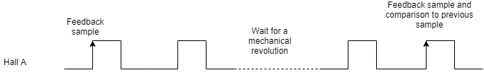
To detect counts per revolution of the selected feedback, an event is triggered on a specific transition of Hall A and is only triggered after as many repetitions as pair poles are specified. This event samples the readings of the feedback, and compares it to the previous event, except in the first event of all, where only the sample is taken. This first event can happen either at the start-up of the drive, or when changes of direction are detected in the halls feedback.
No more than two revolutions should occur before detecting a runaway error.
Hall sensor placement and angle asymmetries
In a brushless servo drive, three Hall sensors are ideally placed 120 electrical degrees apart around the stator. In that perfect case, each Hall state (the 6-step commutation sectors) spans exactly 60 electrical degrees, so the reported rotor angle advances in equal steps.
In practice, mechanical and magnetic imperfections in the Hall placement create asymmetries in the angles associated with each Hall pattern:
Unequal mechanical spacing
If the three sensors are not mounted exactly 120° apart (for example: 118°, 122°, 121°), the points at which each Hall switches will no longer be separated by exactly 60 electrical degrees. As a result, the six sectors become different widths (e.g. 55°, 62°, 58°, etc.), so the “reported angle” associated with each Hall pattern does not represent a uniform angular step.Circumferential offset of the sensor cluster
Even if the sensors are correctly spaced relative to each other, the whole group can be shifted relative to the magnet pattern on the rotor. This shifts the effective electrical zero and can skew the mapping between Hall transitions and actual rotor angle, so the drive commutates slightly early or late in some sectors.Magnet and flux non-uniformity
Variations in the rotor magnetization (non‑uniform flux, pole‑to‑pole differences, or magnet skew) mean each Hall sensor reaches its switching threshold at slightly different physical angles, again distorting the effective sector boundaries.Sensor threshold and alignment tolerances
Each Hall IC has its own switching threshold and hysteresis. Small differences between devices, combined with tiny tilts or height differences in mounting, move each sensor’s switching point a few electrical degrees, adding to the asymmetry.
All of these effects mean that the electrical angle reported by the Hall pattern is not perfectly linear with the true rotor angle: some sectors are effectively “longer” and some “shorter”. This causes commutation angle errors.
How Hall asymmetries can affect the phasing when working with Halls + Incremental encoder
Due to the low resolution of hall sensors, they are usually paired with an incremental encoder that provides higher resolution, allowing the drive to better control commutation and field-oriented control. In a setup where the halls are used as the reference encoder and an incremental encoder as the commutation encoder, hall sensors serve as an absolute reference to determine the real commutation angle during the initial alignment. This process is called Alignment.
For more information about the Alignment procedure, please check https://drives.novantamotion.com/summit/commutation
In a non‑forced phasing with incremental encoder + halls, the drive uses the halls as an absolute reference only at start‑up. The drive moves until it detects the first hall angle transition, then calculates the difference between the electrical angle measured by the drive's reference system and the actual electrical angle.
Due to the earlier-mentioned hall asymmetries, the angle read during non-forced phasing introduces a small error in the drive's angle measurement at the first hall transition. The image below shows the error between the hall sensors' reported angle and the incremental encoder's counts.
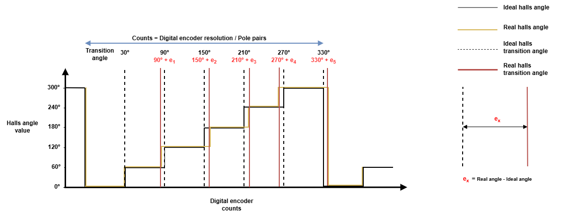
The image only shows the asymmetries observed when moving in the positive direction (0º → 60º → 120º …). This error may not be the same for each transition when moving in the negative direction (0º → 300º → 240º → …).
The error introduced in the commutation angle offset due to improper alignment may have the following consequences
Reduced torque per ampere.
Increased torque ripple and noise.
Higher current for the same load.
Lower max speed or poorer efficiency at high speed.
Hall offset compensation feature
Novanta’s servo drives include a compensation table to minimize the effect of the halls asymmetries by adding a correction value for each transition.
The feature can be configured using the following registers:
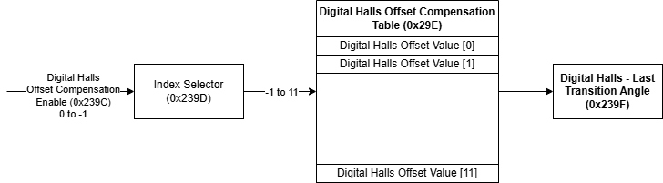
0x239C - Digital halls offset compensation enable
When enabled, the stored compensation values apply to the hall's last transition angle. When disabled, the values are not applied but remain stored in memory for future use.
0x239D - Digital halls offset compensation index
0x239E - Digital halls offset compensation value
These registers allows modifying or consulting a specific compensation value for a given electrical angle and direction (positive or negative). Compensation index selects the table index to modify and compensation value inputs the value into that index
0x239F - Digital halls - Last transition angle
Reports the last transition angle detected by the hall sensor. It can be used to validate the correctness of the compensation values.
What values should be used for offset compensation?
The hall displacement error can be defined as:
Which is also equivalent to:
Where:
Angleideal -> Ideal transition angle (30º, 90º, 150º, 210º, 270º, 330º)
eAngleideal -> Error for a given ideal transition angle
Anglereal -> Real angle (includes the displacement against the ideal angle)
Insert compensation values as error values at each transition.
Each angle has a compensation value depending on the rotor's direction.
Measure all errors against a reference transition with a compensation value of '0'. In the image in https://novantamotion.atlassian.net/wiki/spaces/SS/pages/2209776711, the reference angle is 30º positive.
Other angles can serve as references
Calculate the compensation at the angle opposite to the reference. For example, if the reference angle is 30º positive, set the compensation value for 30º negative.
Example:
Let’s assume that we have the following errors:
Error = 1.5º at 90º when moving in the positive direction.
Error = 0.8º at 90º when moving in the negative direction
Note that the feature works with unitary values, so these errors must be scaled into the range [0.0, 1.0], then:
1.5º should be written as 1.5º/ 360º = 0.0041667
0.8º should be written as 0.8º/360º = 0.00222
To compensate for these values, we should do the following operations:
Write '1' to 0x39D - Digital halls offset compensation index → Selects 90º in the positive direction
Write ‘0.0041667’ to 0x39E - Digital halls offset compensation value → Sets the compensation value for the given angle
Write '7' to 0x39D - Digital halls offset compensation index → Selects 90º in the negative direction
Write ‘0.00222’ to 0x39E - Digital halls offset compensation value → Sets the compensation value for the given angle
Write '1' to 0x39C - Digital halls offset compensation enable → Enables the compensation feature.
Read 0x39F - Digital halls - Last transition angle when transitioning on 90º → Allows to check if the angle applied compensation is the expected one