Gear reducers and multiple feedbacks
Summit servo drives include the option to use several feedback sensors at the same time. The available feedback slots are:
- Reference feedback sensor.
- Commutation feedback sensor.
- Velocity feedback sensor.
- Position feedback sensor.
- Auxiliar feedback sensor.
Only 4 feedbacks can be mapped simultaneously in all of the feedback sensor slots.
This can be used in systems with a transmission gearbox. Having a dedicated position sensor in the load shaft has many advantages, specially compensating transmission effects such as backlash.
The schema of a motion system with a transmission gearbox is depicted below.
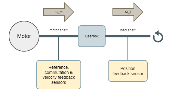
Where is the angular velocity in the motor shaft and
is the angular velocity in the load shaft.
The only feedback sensor that can be placed in the load shaft of a gearbox is the position feedback sensor.
Auxiliar feedback sensor can also be set to the load shaft, because auxiliar feedback is not used for control.
If the gearbox is a reduction type, then , which is the typical use case. The gear ratio information is hold in the register position to velocity sensor ratio, and
.
A widely used parameter for defining gear reducers and gearboxes is the Gear Ratio (GR). GR is defined as , so it is the inverse of the position to velocity sensor ratio.
Gearboxes with are also supported. Then, position to velocity sensor ratio will be > 1.
Example
Consider a mechanical system composed by a motor, which has digital halls and an incremental encoder. Connected to the motor, a gear reducer is present and an absolute encoder is attached to the reducer load shaft. The gear ratio of the gearbox is 80.
Then the configuration would be:
- Reference feedback sensor set to the digital halls.
- Commutation feedback sensor set to the incremental encoder.
- Velocity feedback sensor set to the incremental encoder.
- Position feedback sensor set to the absolute encoder.
- Auxiliar feedback sensor can be set to any of the available encoders.
- Position to velocity sensor ratio = 1 / 80 = 0,0125.
Gear reducer and control loops
The register position to velocity sensor ratio is used inside the Profiler module. The position-velocity cascade control loop schema is the following one:
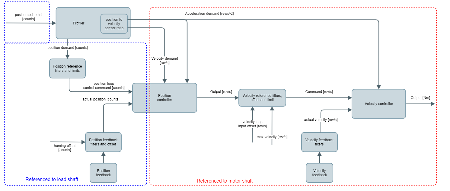
As it can be seen, the position controller has inputs in units from both references: motor and load shafts. This makes that the position controller gain Kp (register Position loop Kp) includes implicitly the gear ratio conversion: .
Further information about control loops can be found in Operation section.