MCB start-up sequence
An MCB device requires an initial start-up sequence of some signals for a proper functionality.
Application start-up
The next diagram shows how the standard start-up sequence must be executed:
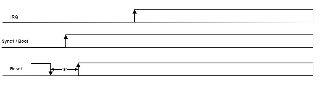
- Reset signal is active low and it is used to hold the MCB device into reset state.
Sync1 / Boot signal is used to indicate the mode of operation of the MCB device. For running application, the Sync1 / Boot signal must be high before the Reset is released (high).
- Irq signal should be used by the connected master device to know when the MCB device is ready to receive data through the bus.
After boot-up the slave takes control of the Sync1 / Boot signal. After Reset is released, configure the master Sync1 / Boot pin as input.
Reset setup time (tsr) must be at least 100 us.
Bootloader start-up
An MCB device is updatable if it is started in bootloader mode. The next sequence shows how to run the bootloader mode:
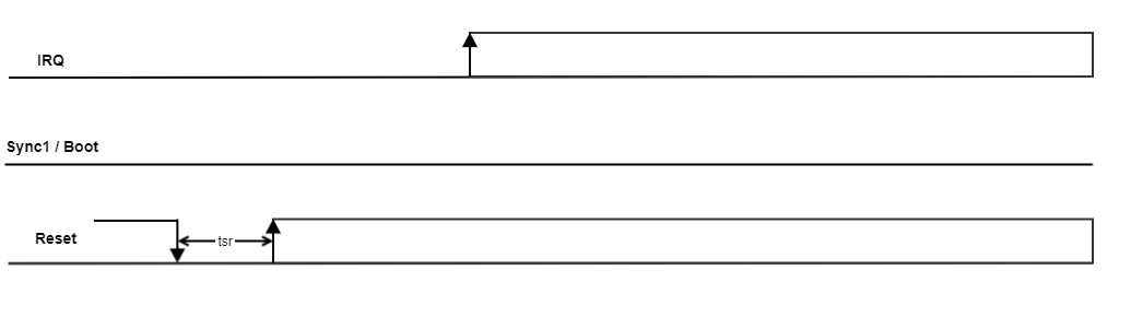
- Reset signal is active low and it is used to hold the MCB device into reset state.
Sync1 / Boot signal is used to indicate the mode of operation of the MCB device. For bootloader operation, the Sync1 / Boot signal must be low before the Reset is released (high).
- Irq signal should be used by the connected master device to know when the MCB device is ready to receive data through the bus.
After boot-up the slave takes control of the Sync1 / Boot signal. After Reset is released, configure the master Sync1 / Boot pin as input.
Reset setup time (tsr) must be at least 100 us.
Boot mode is reachable through the communication bus once the application mode is running.