MCB synchronisation
MCB has some external synchronization mechanisms. In particular, it can use two signals that provide synchronization to the drive and from the drive. These signals are the following:
SYNC0
This signal enters the drive from the external world and synchronizes the PWM cycles (causing the control loops to be synchronized as well). Synchronization happens by means of an internal PLL that adapts the PWM frequency of the drive to the Sync0 signal provided. It is important that the jitter of the signal is minimal
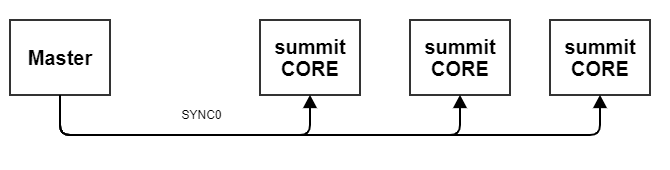
The usage of this signal may be desired for example to ensure that several axis execute their loops and update their set-points at the same time. It must have the lowest jitter possible.
This signal is useful when an external time reference is available on the whole system like in EtherCAT networks using Distributed Clocks where the clock reference comes from the first slave of the network.
The way the implemented PLL algorithm works is described below
Phase correction
To adjust the period of the PWM to lock it into the synchronization signal, a phase correction is performed. To do this, the PWM elapsed ticks are measured at the moment when the synchronization pulse happens, and are compared to the number of ticks that would equal the desired alignment phase. Overflows are accounted for and wrapped. This is considered to be the phase error. The phase error is scaled by a proportional constant to reduce the control action
PhaseError Phase difference between the moment where the synchronization signal is detected and the desired alignment phase of the PWM
TicksElapsed_PWM MCU ticks elapsed on current PWM cycle
TicksDesiredPhase_PWM Phase of a PWM cycle to which we want to align the synchronization signal
K_p Proportional constant to reduce the action of the phase error
Frequency feedforward
A frequency feedforward term is calculated by measuring the synchronization signal period using the ECAP hardware module in the MCU, which calculates the time difference in ticks between two rising edges of the signal.
This measurement is then scaled to obtain the equivalent PWM ticks. To obtain the scaling factor, the drive must know what the frequency of the synchronization signal is beforehand.
Freq_sync is the theoretical frequency of the synchronization signal in Hz
Freq_PWM is the theoretical frequency of the PWM in Hz
K_scaling is the ratio between the synchronization signal frequency and the PWM frequency
Ticks_sync Measured duration of the synchronization signal in MCU ticks
CorrectedTicks_PWM is equivalent amount of ticks in the PWM timer required to lock with the synchronization signal
Saturation
To avoid undesired or dangerous behaviours, a saturator limits the PWM period ticks to be applied. The frequency deviation caused by this algorithm will never be greater than 10% of the default PWM period ticks.
Fitering
Some external factors such as jitter in the syncronization signal or imprecisions in the frequency and phase measurements can affect the PWM frequency adjustment. This effect can be minimized by adding an averaging low pass filter at the output of the phase correction block.
The filter used is a first order IIR digital filter:
Note
An excessively low cutoff frequency can make the algorithm useless since the frequency and phase correction would become too slow to properly compensate for the drift.
SYNC0 PLL parameters
For the PLL to work, the following four parameters must be configured first.
Name | Key | CoE id | Value range | Default value | Units |
|---|---|---|---|---|---|
Sync. signal frequency | 0x0643 | 0x2643; 0x00 | UINT32 | 1000 | Hz |
Sync. signal PLL filter cutoff frequency | 0x0644 | 0x2644; 0x00 | UINT32 | 100 | Hz |
Sync. signal PLL phase | 0x0645 | 0x2645; 0x00 | 0.0 - 1.0 | 0.25 | - |
Sync. signal PLL Kp | 0x0646 | 0x2646; 0x00 | - | 0.01 | - |
Sync. signal frequency: The synchronization signal (SYNC0) frequency must be specified in this parameter.
Sync. signal PLL filter cutoff frequency. The PLL implementation uses a low pass filter to average any jitter that appears in the adjustment process. This parameter specifies the cutoff frequency of the low pass filter.
Sync. signal PLL Kp. This parameter applies a proportional scaling to the phase error between the PWM period and the synchronization signal period.
Sync. signal PLL phase. This parameter specifies the phase of the PWM cycle that should be aligned to the synchronization signal. This parameter is unitary, being the value 0.0 equal to 0 degrees and 1.0 being 360 degrees.
Choosing a good SYNC0 frequency
For the PLL to work properly, the frequency of the SYNC0 signal must be an exact multiple of the selected PWM frequency of the drive. A table of possible combinations is provided below for each frequency in the Everest product as an example.
PWM frequency | Allowed SYNC0 frequencies |
|---|---|
10 kHz | 10Hz, 20Hz, 40Hz, 50Hz, 80Hz, 100Hz, 200Hz, 500Hz, 1000Hz, 2000Hz |
20 kHz | 10Hz, 20Hz, 40Hz, 50Hz, 80Hz, 100Hz, 200Hz, 500Hz, 800Hz, 1000Hz, 2000Hz |
50 kHz | 10Hz, 20Hz, 40Hz, 50Hz, 80Hz, 100Hz, 200Hz, 500Hz, 1000Hz, 2000Hz |
100 kHz | 10Hz, 20Hz, 40Hz, 50Hz, 80Hz, 100Hz, 200Hz, 500Hz, 1000Hz, 2000Hz |
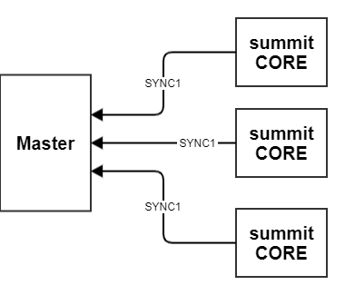
SYNC1
This signal is managed by the drive. Each rising edge marks when a control loop is executed.
This signal is useful when upper control loops of the MCB master have to be synchronized with MCB slave.
The use of this signal is safer than SYNC0 but only allows synchronize one master with one slave. On Multi-axis systems where synchronization is critical SYNC0 must be used.
Sync. signal configuration
The usage of this signal can be configured using the following parameter:
Name | Key | CoE id | Value range | Units |
|---|---|---|---|---|
Sync. signal configuration | 0x641 | 0x2641; 0x00 | 0 - Disabled 1 - Only SYNC0 2 - Only SYNC1 3 - SYNC0 and SYNC1 | - |
Note
This parameter can only be changed when the power stage is disabled
Some of the drive communication options demands synchronize the axis with the communication core in order to reach the communication specifications.
Sync method | Sync reference | |
|---|---|---|
EtherCAT Pre-op | None | - |
EtherCAT Freerun | None | - |
EtherCAT SM | None | - |
EtherCAT DC | Sync0 | Ethercat Sync0 signal |
Monitoring/Disturbance | Sync0 | An internal hardware reference signal |
To assure a correct synchronization, the PLL settings may be adjusted, the sync signal frequency and mode are automatically modified during the transitions.
EtherCAT DC mode: To reach the 2 cycles (ECAT) of latency the axis must be synchronized with the EtherCAT network DC cycle. The Sync0 EtherCAT signal is used as a reference synchronization signal.
Monitoring and disturbance: The signal injection or data reception guarantees that data are applied deterministically at the desired high frequency. The sync signal is generated internally with a hardware pwn peripheral, at 2Khz.
Practical example - SYNC0
In the following animations, the difference between using SYNC0 to synchronize two different axis and not using it can be appreciated. Both the yellow and blue signals show the Phase A PWM of two different axis, while the purple signal shows the SYNC0 synchronization pulse.
Axis not synchronized
It can be seen how in time both PWMs drift away.
Both axis synchronised
On every SYNC0 rising edge, the PWMs get synchronized