Position modes (CSP, PP, IP, P)
This mode is used to command the position of the actuator. It requires a proper configuration of the commutation sensor.
The commutation sensor configuration process is described in the Commutation section.
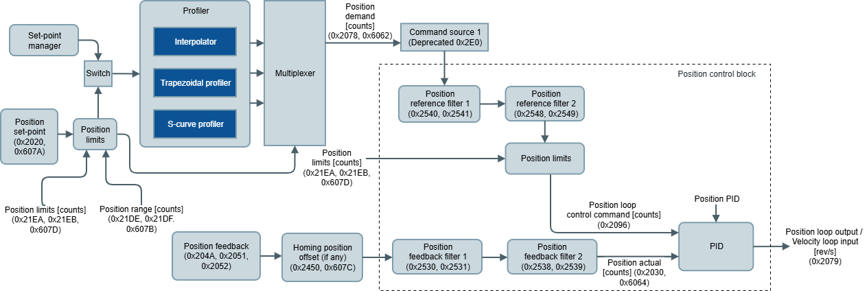
Position limit block is available to protect the system in front of mechanical limits or other factors or to allow endless positioning in case of, for example, rotary systems. Max position and min position determine these limits and are applied to position demand. The output of the PID is directly connected to the velocity loop input block of the Velocity modes (CSV, PV, V).
This mode can be sourced directly from the network or through the profiler mode. This last one allows multiple configurations:
Cyclic synchronous position (CSP)
Profile position (PP): trapezoidal and s-curves
Interpolated position (IP): linear and 5th polynomial
The position feedback block delivers the actual position of the system based on the position feedback sensor.
The drive supports multiple feedback options. Take a look at the Feedbacks section.
The implemented PID module follows the next block diagram:
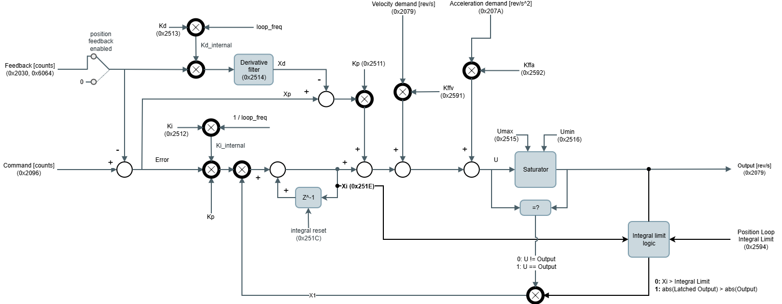
The output of the control loop at the kth sample is:

Where:
U is the output before entering in the saturator, in mechanical revolutions per second [rev/s].
The output after saturator is limited to the values Umax and Umin, so if the I signal is outside these parameters, the output is clamped.Command c is the Command signal (Output of the Reference + Filters + offset), in [counts].
Feedback f is the Filtered Feedback signal (Output of the Feedback + Filters), in [counts].
Kp, Ki and Kd are the PID gains. Kp in [(rev/s)/counts], Ki in [Hz] and Kd in [s2].
We don't have a way to export this inline extension.Kffv, Kffa are the feed-forward velocity and acceleration gains, respectively. Kffv is non-dimensional, Kffa in [s].
ademand is the acceleration demand, in [rev/s2].
vdemand is the velocity demand, in [rev/s].
xp is the proportional path:+
xi is the integral path:
where x1 is:
The integral accumulator value can be reset at any time externally.xd is the derivative path:
Derivative incorporates also a derivative IIR filter, where c1 and c2 are the derivative filter coefficients:T is the control loop period, in [s], and
, in [s], is the reciprocal of the desired filter bandwidth
The output of the position controller is connected to the velocity command (before the filters and offset) of the velocity control.
All position modes work with a PID controller and the related registers are:
0x2592 - Position loop Kffa (Kffa)
0x2591 - Position loop Kffv (Kffv)
0x251E - Position loop integral value is the integral accumulator value (xi).
0x251C - Position loop integral reset allows to reset the integral part (integral reset).
0x2078 - Position demand, 0x6062 - Position demand value is the reference input of the PID. It's an output of the profiler.
0x2079 - Velocity demand is an output of the profiler.
0x207A - Acceleration demand is an output of the profiler.
0x2096 - Position loop control command is the command value after the filter and offset is applied (Command signal from the diagram).
0x21E2 - Position control loop error, 0x60F4 - Following error actual value is the difference between the reference and feedback values in the control loop.
0x2030 - Actual position, 0x6064 - Position actual value is the feedback input after the filter is applied (Filtered Feedback signal from the diagram).
0x2020 - Position set-point, 0x607A - Target position is the target commanded to the position modes.
On the other hand, the implemented controller supports additional features:
Position feedback enabled allows opening the loop of the PID. It is configured with register 0x2510 - Control loops feedback options. The feedback path is removed from the real feedback signal and it forces a value of 0.
0x2520 - Position & velocity loop rate contains the update rate of execution of the PID.
0x2519 - Position loop status contains information about PID functionality;
Loop enabled. This flag activates if the current loop is enabled and in use.
Upper saturator active (momentary). This flag activates when the current loop is saturating on the upper limit. The flag deactivates when the upper saturation is not happening anymore.
Lower saturator active. This flag activates when the current loop is saturating on the lower limit. The flag deactivates when the lower saturation is not happening anymore.
Command limit. This flag activates when the position loop control command signal is outside the max. position and min. position limits. The flag deactivates when the position loop control command signal is inside the position limit thresholds.
Set-point limit. This flag activates when the position set-point is outside the max. position and min. position limits. Under this situation, the position demand is limited to the nearest position limit. The flag deactivates when the position set-point is inside the position limit thresholds.
0x2522 - Control loops option code allows to enable or disable the continuity of the PID output. If enabled, it would prevent instantaneous undesired PID outputs. Also, changing the PID constants can cause discontinuities in the control output.
If continuity is going to be used, it is recommended to have a non-zero integral constant.
Do not use this feature while tuning the system since it could be misleading.
0x21F1 - Position window and 0x21F2 - Position window time are used to determine when position demand has been reached by the actual position. Depending on the selected feedback, the system environment, and the drive configuration the velocity ripple amplitude changes. These configurable parameters are used to determine what is the maximum tolerable error between the two mentioned parameters.
0x21EC - Position following error window, 0x6065 - Position following error window and 0x21ED - Position following error timeout, 0x6066 - Following error time out are used to determine when the actual position is not following the position demand as expected, it means the error between them is too big. The response of the system if the following error is detected is configurable by the 0x2612 - Position following error option code.
Integral limit and anti-windup protection logic uses the information from the accumulated value (Xi) in the integral path and the actual PID output (Output [rev/s]) to enable/disable the integral path:
When the accumulator of the integral path overcomes the value defined in the 0x2594 - Position loop integral limit:
The integral path is disabled (X1 = 0)
The integral accumulator value is set to the integral limit
The output of the PID is stored in a variable
For restoring the integral path (X1 = 1), the next conditions are required:
If the new value PID output is smaller than the stored one, the integral path is restored.
0x2594 - Position loop integral limit - sets the value for comparison of the integral term (Xi)
0x251E - Position loop integral value - indicates the value of integral term (Xi)
0x251C - Position loop integral reset - resets the integral value of the velocity control loop
It is not recommended to use this feature together with the control loop option “continuity” and live-changing the PID parameters. The continuity feature of the control loops recalculate the integral accumulator to keep the value of the output. Therefore, under some scenarios, the new integral accumulator is higher than the limit and the continuity feature might not work as expected.
Filters and offset
Additionally to the PID controller, two biquad filters in cascade are available for both PID input sources: Reference and feedback. The purpose of these filters differs on every application, but basically they help to improve feedback readings or compensate undesired system dynamics. There are multiple configurations for every filter:
Low pass filter
High pass filter
Band pass filter
Peak filter
Notch filter
Low shelf filter
High shelf filter
The next parameters configure every filter type:
Filter type | Frequency | Q-factor | Gain (dB) |
|---|---|---|---|
Low pass | X | X | - |
High pass | X | X | - |
Band pass | X | X | - |
Peak | X | X | X |
Notch | X | X | - |
Low shelf | X | - | X |
High shelf | X | - | X |
The related parameters for filter configuration are:
0x2540 - Position reference filter 1 type & 0x2548 - Position reference filter 2 type
0x2541 - Position reference filter 1 frequency) & 0x2549 - Position reference filter 2 frequency
0x2542 - Position reference filter 1 Q-factor) & 0x254A - Position reference filter 2 Q-factor
0x2543 - Position reference filter 1 gain) & 0x254B - Position reference filter 2 gain
0x2530 - Position feedback filter 1 type) & 0x2538 - Position feedback filter 2 type
0x2531 - Position feedback filter 1 frequency) & 0x2539 - Position feedback filter 2 frequency
0x2532 - Position feedback filter 1 Q-factor) & 0x253A - Position feedback filter 2 Q-factor
0x2533 - Position feedback filter 1 gain) & 0x253B - Position feedback filter 2 gain
Additional feedback sensor
The drive allows activating additional extra feedback for monitoring or other purposes. This feedback is activated selecting it through the auxiliary feedback sensor. The readings are available on auxiliary feedback value in raw format (cnt). Any mappable feedback used for position and velocity can be used as an auxiliary feedback sensor.
Endless position applications
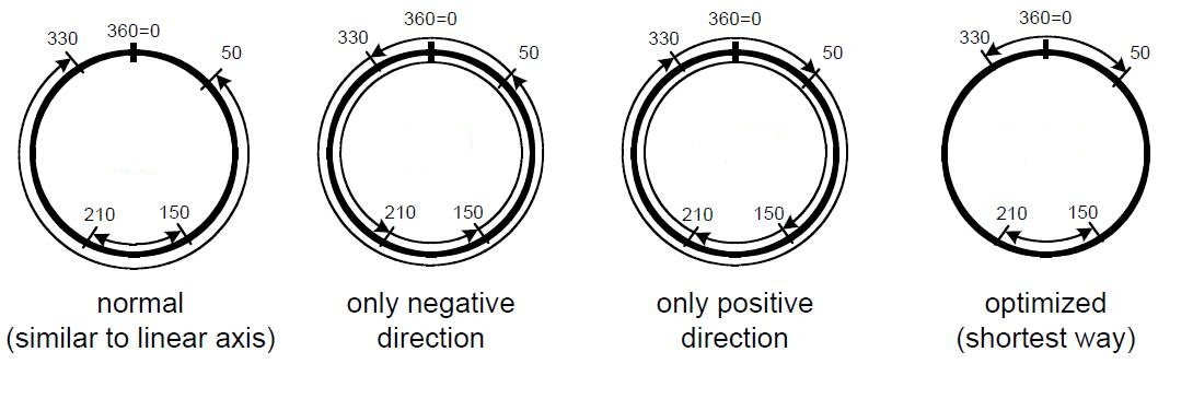
Applications where position control is used but the system position range is infinite (rotary systems) can be described into the drive by using the 0x21DF - Max position range limit, 0x607B - Position range limit and 0x21DE - Min position range limit, 0x607B - Position range limit. On reaching or exceeding these limits, the position set-point and position actual wrap automatically to the other end of the range. Usually, when these registers are required they define a complete system revolution.
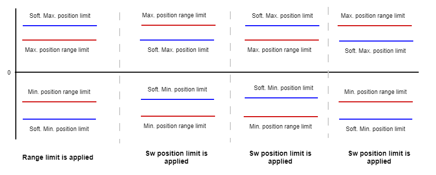
If software position limits and position range limits are enabled, the more restricted is applied. Software position limits are chosen in case of conflict:
Following figure shows examples of the different position option movement types. In this example, the min position range limit is 0° and the max position range limit is 360°.
Position mode (P)
Position (P) mode uses the above control scheme, connecting the position set-point input from the application directly to the position demand signal mentioned above.
Note
Set-points will begin being taken into account after transitioning to the "operation enabled" state on the drive.
Cyclic synchronous position mode (CSP)
Cyclic Synchronous Position mode (CSP) uses the above control scheme as well but connects the position demand to the linear profiler of the set-point manager.
Note
The profile will generate depending on the selected 0x21C8 - Profiler latching mode. If latching is disabled, the linear profile starts immediately upon a change of position set-point. If latching is enabled, the linear profile starts after a change of position set-point and its confirmation through lathing bit from the control word.
Warning
It is mandatory to configure the 0x21EF - Interpolation time mantissa and 0x21F0 - Interpolation time exponent. The value of these parameters will determine how the linear profile will be performed. The product of these two parameters should match the time that will take to update the current quadrature set-point. More information about the linear profile can be found in the Set-point manager and interpolator buffer section.
Profile position (PP)
Profile position (PP) uses the same control scheme as CSP. The difference is the selected profile mode in the set-point manager. Instead of a linear profile used to interpolate position set-points, a more complex profile is generated taking into account user-configurable parameters. These parameters are:
0x2026 - Profiler max. acceleration, 0x6083 - Profile acceleration
0x2027 - Profiler max. deceleration, 0x6084 - Profile deceleration
0x2028 - Profiler end velocity, 0x6082 - Profile end velocity
Profile end velocity is available in COMOCO Drives (-NET-) with firmware 2.10.0 and beyond
In this mode, a trapezoidal profiler is used but other can be used. Further information about the trapezoidal and other motion profiles can be found in the Set-point manager and interpolator buffer section.
This mode accepts new set-points by validating them through the control word register.
Example
The following picture shows a trapezoidal velocity trajectory in a profile position (PP) movement.
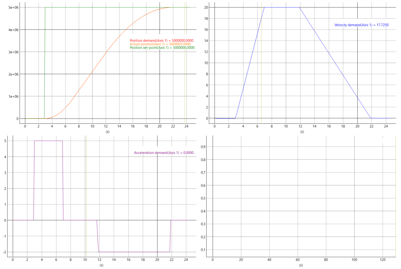
Diagram of a trapezoidal profile move with an end velocity
The following diagram shows a trapezoidal motion trajectory in a profile position (PP) movement with end velocity ≠ 0
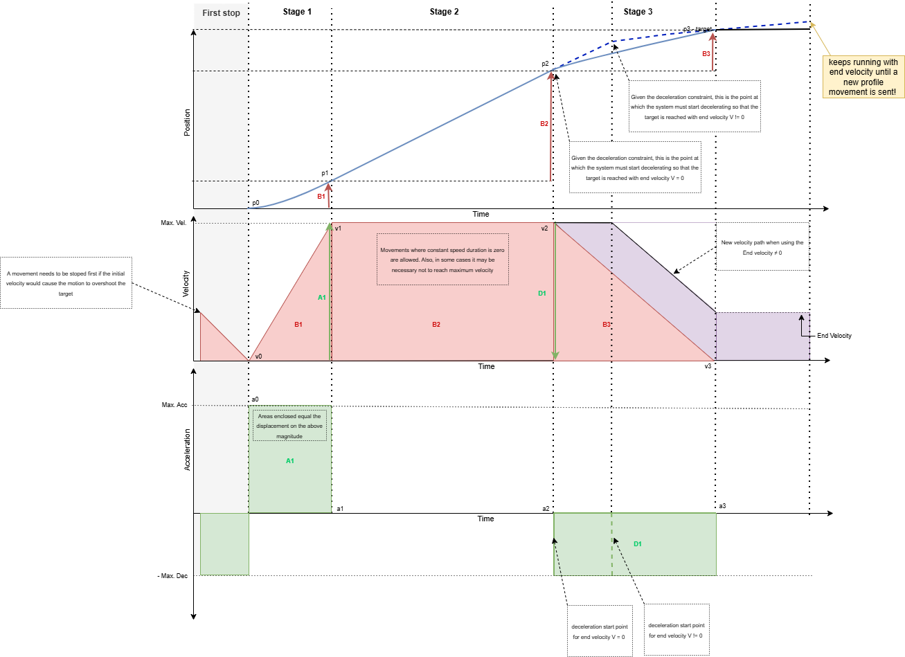
If end velocity is not equal to 0, the system will continue running with the configured end velocity until a new profile movement is sent.
S-curve profile position (SPP)
The S-curve profile position mode (SPP) uses the same control scheme as PP. The main difference between SPP and PP is that in PP the velocity follows a trapezoidal trajectory (acceleration, constant velocity, deceleration), whereas, in SPP, the transition points of the trapezoidal trajectory are instead linked by 5th-degree polynomials. This creates a smoother and continuous velocity trajectory, and the jerk in the system is reduced. The position trajectory also becomes smoother than in PP mode. In this mode, the set-point manager parameters required are the same as in PP. These are.
Profiler max. velocity
Profiler max. acceleration
Profiler max. deceleration
Further information about the S-curve profile can be found in the Set-point manager and interpolator buffer section.
This mode accepts new set-points by validating them through the control word register.
Example
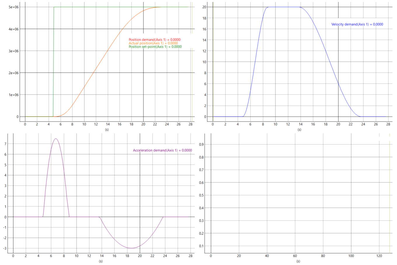
The following picture shows an equivalent movement of the example above, but using a S-curve velocity trajectory in a S-curve profile position (SPP) movement.
Note
Currently, the s-curve trajectory is calculated based on an underlying trapezoidal trajectory. The velocity polynomial curve must cover the same area as the trapezoidal velocity curve in the same amount of time. Because of this, latching a new movement during the deceleration stage of the movement may lead to a temporary position overshoot.
Interpolated position (IP)
Interpolated Position mode (IP) behaves in a similar fashion to CSP, in the way that uses a linear interpolator in the profiler module to operate. The main difference, however, is that the set-points of the interpolator are provided by the interpolation buffer.
In this mode, the interpolation buffer allows the user to append a buffer of positions in the drive that will be fed to the set-point manager at a constant rate given by the interpolation time mantissa and interpolation time exponent . More information about the interpolation buffer can be found in the Set-point manager and interpolator buffer section.
Warning
It is mandatory to configure the interpolation time mantissa and interpolation time exponent for this mode to work. The value of these parameters will determine how the interpolation will be performed. The product of these two parameters should match the time that will take to update the position set-point.
Position velocity time (PVT)
Position velocity time (PVT) behaves in a similar fashion to IP. In this mode, the Set-point manager and interpolation buffer allow the user to provide the drive with sets of final position, velocity, and movement duration. Interpolation time mantissa and magnitude order will not be necessary for this mode because interpolation time will be extracted from the time introduced into the buffer of the set-point manager directly. These sets of points are then fed to the set-point manager, which will use the PVT profiler to generate 5th-degree polynomial trajectories that reach each position set-point at the specified velocity in the given time duration.
Warning
The generated PVT profile does not take into account the system limits to generate its trajectories. This means that the main device/instance should take care of ensuring that the requested trajectories can be physically performed within the average limitations of the motor.