Secondary SSI
Additionally to the main absolute encoder channel, an additional SSI encoder is supported by Summit servo drives. This covers the cases where dual absolute is required but BiSS-C daisy chain devices are not available.
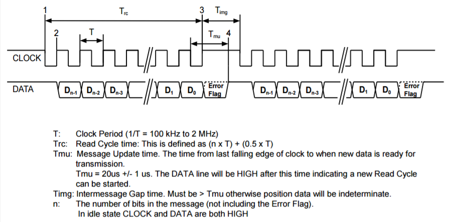
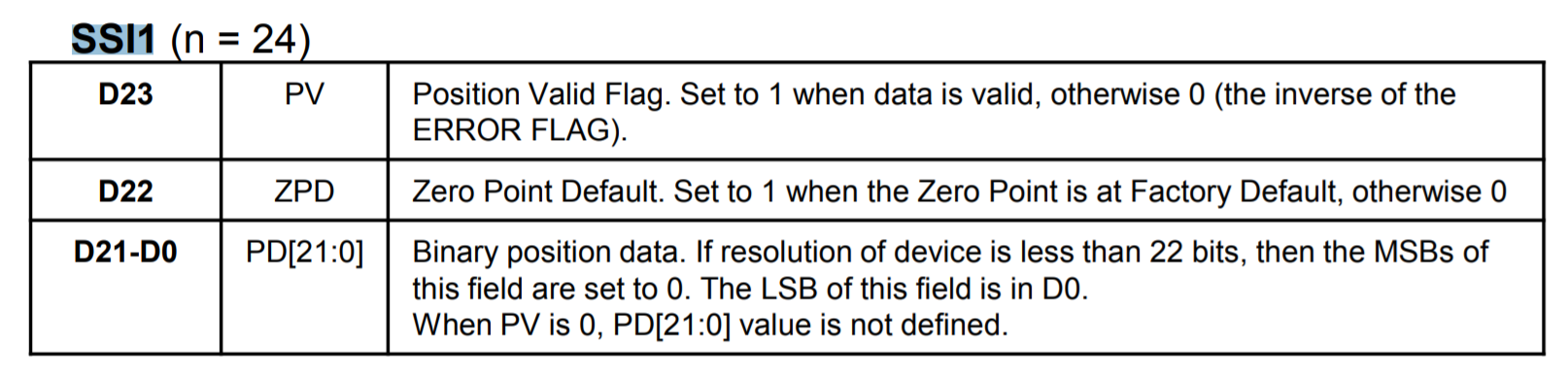
A wide variety of SSI are supported by Summit servo drives. However, every feedback product has its own protocol over the SSI. Below there is an example based on a protocol of the IncOder product family.
A set of parameters are available to the user to adapt the secondary SSI interface to the different supported protocols
- Frame size. Indicates the total number of bits of the frame, including position and any special bit.
Error tolerance. The drive is able to detect an incorrect frame (for example readings the position valid flag of the SSI1). If an incorrect frame is detected, it is dropped and the drive keeps the last read as current position actual. However if too many followed errors are detected, the drive generates a fault and stops the operation. This register specifies the number of errors accepted before generating the fault.
Setting a 0 value will ignore any error from the encoder.
Reading wait cycles. Control loops might work at high rates, so the minimum period between SSI readings might be higher and the drive must wait some control loops before requesting new data.
- Polarity. Indicates the direction of rotation of the SSI encoder. 0 value applies standard polarity (read directly from the feedback) and a value different than 0 reverses the polarity.
Frame type. Indicates the format of the received frame.
For unsupported frame types, use raw or raw gray modes. These modes allow reading the position from any frame type without processing special bits such as CRC or error flags.
Position bits. Indicates the number of bits used for position readings.
Note
The device calculates its own multi-turn data to allow covering the whole position variable range. Use position range configuration if the systems need to work only in the absolute encoder range.
Single-turn bits. Indicates the number of the position bit used for single-turn.
This information is used by the drive to compute the angle commutation properly. For multi-turn absolute encoders, this information gives the reference of 1 mechanical revolution to the drive.
For single-turn absolute encoders, position bits must be equal to single-turn bits.
Note
Writing the following parameters will cause the software multi-turn (multi-turn part calculated by the driver) to be reset to 0: Frame size, Polarity, Frame type, Position bits, Single-turn bits, Position start bit, and Position Offset.
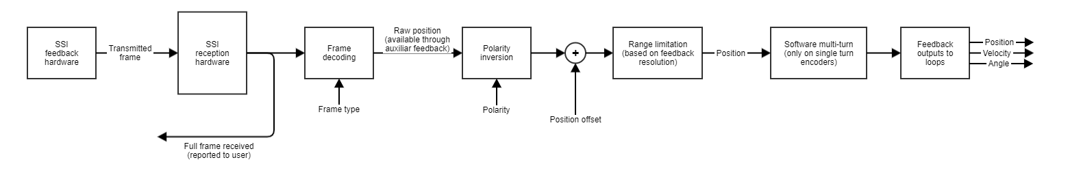
- Position offset. Adds an offset to the read encoder position (after polarity has been applied). Negative values on this parameter shift the overall position in the negative direction and positive values shift it to the positive direction
- Position. Shows the encoder position value taking into account the polarity, position offset, and (if available) software multi-turn.
- Position start bit. Defines how many bits the position information is displaced from the LSB in the serial absolute feedback frame.
- Full frame. Contains the last received frame including special bits, for debugging purposes