XCR - Signalling LEDs
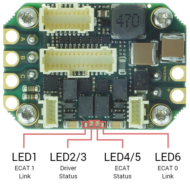
The drive provides information through 6 signalling LEDs:
- EtherCAT 0 link: LED 6 green
- EtherCAT 1 link: LED 1 green
- Driver Status: LED2 & LED3 (one bi-color).
- EtherCAT Status: LED4 & LED5 (one bi-color).
Start-up Sequence
After power on the drive LEDs sequence is the next one:
| Protocol | EtherCAT 0 Link | EtherCAT 1 Link | Drive Status | EtherCAT Status |
|---|---|---|---|---|
| CANopen | See below | See below |
|
|
| EtherCAT | See below | See below |
|
|
| FTP boot mode | See below | See below | Reserved |
|
Driver Status LEDs
Two LEDs indicate driver status. Note that both LEDs are grouped into a single red/green package.
| Identified | Name | Colour | Meaning |
|---|---|---|---|
| LED2 | RESERVED | Green | Reserved |
| LED3 | FAULT | Red | LED is on when an error event has occurred and the drive is trapped in the Fault state. |
EtherCAT Status LEDs
Four LEDs provide information regarding communication status according to EtherCAT specification.
The EtherCAT green and red LEDs (shared with CANopen communication) indicate the EtherCAT status. The green LED is the RUN LED, and the red LED is the ERROR LED. Next table shows their states meaning:
LED4 - RUN LED state | EtherCAT slave status | LED5 - ERROR LED state | EtherCAT slave status | |
|---|---|---|---|---|
| Off | INIT | Off | No error | |
| Flickering | BOOTSTRAP | Blinking | Invalid configuration | |
| Blinking | PRE-OPERATIONAL | Single flash | Local error | |
| Single Flash | SAFE-OPERATIONAL | Double flash | Watchdog timeout | |
| On | OPERATIONAL | |||
The two green LEDs at the sides are the LINK 0 and LINK 1 LEDs. The LINK LEDs indicates the state of the EtherCAT physical link activity:
LINK LED state | Slave State |
|---|---|
| Off | Port closed |
| Flickering | Port opened (activity on port) |
| On | Port opened (no activity on port) |
CANopen Status LEDs
One Bi-color LED (shared with EtherCAT communication) provides information about the CANopen communication status, according to CiA 303-3 recommendations. The green LED is the RUN LED, and the red LED is the ERROR LED.
ERROR LED indicates the status of the CAN physical layer and errors due to missed CAN messages (sync, guard or heartbeat). Next table the meaning of the ERROR LED states:
LED5 - ERROR LED state | Concept | Description |
|---|---|---|
Off | No error | Device is in working condition. |
Single flash | Warning limit reached | At least one of the error counters of the CAN controller has reached or exceeded the warning level (too many error frames). |
Double flash | Error control event | A guard event (NMT-slave or NMT-master) or a heartbeat event (heartbeat consumer) has occurred. |
Triple flash | Sync error | The sync message has not been received within the configured communication cycle period time out. |
On | Bus off | The CAN controller is bus off. |
RUN LED indicates the status of the CANopen network state machine. Next table shows the meaning of the RUN LED states:
LED4 - RUN LED state | Concept | Description |
|---|---|---|
Off | Off | The device is switched off |
Blinking | Pre-operational | The device is in state PRE-OPERATIONAL |
Single flash | Stopped | The device is in state STOPPED |
On | Operational | The device is in state OPERATIONAL |
The two green LEDs at the sides are the LINK 0 and LINK 1 LEDs. The LINK LEDs indicates the state of the Ethernet physical link activity:
LINK LED state | Slave State |
|---|---|
| Off | Port closed |
| Flickering | Port opened (activity on port) |
| On | Port opened (no activity on port) |