Tuning the brake current control
Summit series devices are able to control the current applied to a brake with a PI control loop operating at a fixed update rate of 1 kHz. This mode of operation requires of an external current sensor, as no current sensor is provided by the drive, whose output will be read using one of the two available general-purpose ADC inputs (GADC).
Current sensing considerations
When operating in current control mode, samples on the selected GADC are synchronous with the center of the HIGH pulse of the brake PWM signal (as an exception to the general rule defined in Inputs and outputs). This allows the current sensor to be placed both on low-side or high-side of the brake circuit.
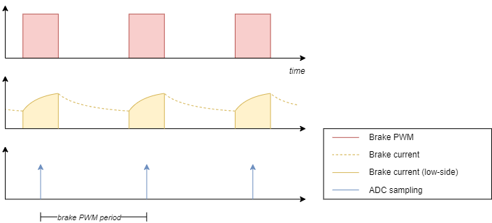
Any delay introduced by the current sensing circuit will cause a temporal shift of the sensing point. This could create an under-estimation of the sensed current, as samples will be made earlier in the rising curve. In scenarios with low-side sensing and a low duty cycle, this could even cause the sample to fall in the no-current area, making the measurement impossible. The output of the current sensor must be compared to the brake PWM to verify that samples are being taken in the valid area.
The overall gain of the current sensing circuit must be low enough to not exceed the range of the GADC for the maximum current expected to be sensed. Common values usually fall in the range from 2 V/A to 20 V/A.
Configuring the GADC
The GADC must be configured to properly convert the input to the brake current value. This is done with a gain and offset registers, as described on Inputs and outputs.
After applying the GADC gain and offset the reported brake current value will be so, in order to have
:
The gain G' must be configured first to compensate all the accumulated gains (sensing resistor, sensing amplifier, sampling and normalization)
The offset K' must be configured second to trim the value so the reading is zero when no current is being applied to the brake
Example: Suppose a setup with a 5 mΩ sensing resistor and a 250 V/V amplifier.
The configured gain G' should be
Tuning the control loop
On MotionLab3, create an empty workspace
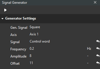
Click on Signal generator and configure the following parameters on the Signal Generator panel:
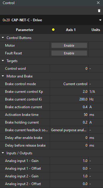
Using the Drive inspector, add the following parameters to the Control panel:
Create a Scope and the register Analog input value (1 or 2) to the plot
On the Control panel, set:
Brake control mode → Current control
Brake current feedback source → General purpose analog input (1 or 2), the GADC being used
Analog input (1 or 2) - Gain → The gain calculated on Configuring the GADC
On the Scope, press the play button
Adjust analog input (1 or 2) - Offset to make the plotted value be 0
On the Control panel set Control word → 6
This will put the state machine on Shutdown state
On the Generator Settings panel, press the play value
This will send 7 and 15 commands to the Control word, making it transition from Switch on to Switch on + Enable repeatedly
The frequency can be modified on the panel
Adjust the remaining parameters to make the brake disengage and engage on every cycle
Brake current control Kp → Proportional constant of the brake control loop
Brake current control Ki → Integral constant of the brake control loop
Brake activation current → Brake current demand at the beginning of the activation
Activation brake time → Time in which the Brake activation current is being applied
Brake holding current → Brake current demand after the Activation brake time
Delay after enable brake → Time between engaging the brake and deactivation of the power stage
Delay before release brake → Time between activation of the power stage and disengaging the brake
Tip: Start the tuning without activation current by setting Activation brake time → 0 ms so the drive commands only the holding current. Delay after enable and the Delay before release brake should also be set to 0 ms. Without these features, configuring the Brake current control Kp and Brake current control Ki to tune the control loop will be easier. The remaining parameters can be adjusted once the control loop is tuned.