Connectors Guide
This chapter details the Titan Go Servo Drive connectors and pinout.
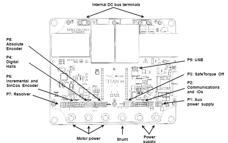
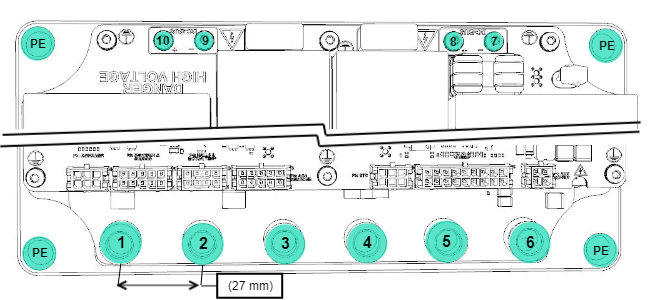
Supply, shunt and motor terminals
| Power terminals | |||
|---|---|---|---|
1 to 6: M8 female terminal, 27 mm pitch. ERNI 225872. 7 to 10: M3 torx screw terminal. PE holes: 9 mm diameter. | |||
Pin | Signal | Function | Screw size |
1 | PH_C | Motor phase C (Do not connect for DC and voice coils) | M8 |
2 | PH_B | Motor phase B (Negative for DC and voice coils) | |
3 | PH_A | Motor phase a (Positive for DC and voice coils) | |
| 4 | SHUNT_OUT | Shunt braking transistor output (Shunt braking resistor should be connected between +POW_SUP and SHUNT_OUT) | |
| 5 | GND_P | Power ground connection (Isolated from logic GND and Protective Earth) | |
| 6 | POW_SUP | Power supply positive | |
| 7, 9 | DC_BUS- | Internal DC bus negative. Internally connected to GND_P but not intended as power supply terminal. Used for additional DC link capacitance. | M3 |
| 8, 10 | DC_BUS+ | Internal DC bus positive. Not intended as power supply terminal. Used for additional DC link capacitance. Titan includes an internal capacitor soft precharge circuit, removing the need for external precharge relays. | |
| Plate | PE | Protective Earth. The assembly screws must be used as earthing connectors. | M8 |
| Notes | |||
| |||
Extra capacitance
It is recommended to add extra capacitance to the main DC supply. The Titan Go has minimal DC bus capacitance that is enough to filter high frequency currents and is enough for battery powered applications. However it could not be enough in some cases and could damage the power supply by demanding excessive current ripple. Add at least a total capacitance of 5 µF/ A (motor phase RMS) to avoid stressing the power supply and minimize EMI problems. Use good quality DC link metalized polymer film capacitors with low ESR (suggested polypropylene).
Ring terminals and screws
Due to the high current ratings, ring terminals and screws are needed for the power terrminals. Following are shown the recommended part numbers.
| M8 screw | Assembly | |
|---|---|---|
| Description | M8 allen screw, 12 mm length |
Maximum torque The maximum torque applied to the screws must never exceed 9 Nm. It can damage the connector and also the printed circuit board. The following picture shows the correct order of the mechanical elements and extra comments for the assembly. 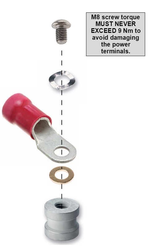 |
| Part number | RS-Pro232-8322 | |
| Distributor codes | RS 232-8322 | |
| Crinkle washer | ||
| Description | M8 stainless steel crinkle washer | |
| Part number | Duratool D00829 | |
| Distributor codes | Farnell 1614006 | |
| Ring terminal | ||
| Description | M8 insulated ring terminal, 2 AWG cable | |
| Part number | Molex 0190710285 | |
| Distributor codes | Digi-Key WM13727-ND Mouser 538-19071-0285 | |
| Brass washer | ||
| Description | M8 brass washer | |
| Part number | RS-Pro 483-2637 | |
| Distributor codes | RS 483-2637 | |
Micro Fit 3.0 connectors mating
All Titan Go Servo Drive signal and communication connections are based in Molex Micro-Fit™ 3 mm pitch connectors. Multi-core crimped cables can be used for wiring inputs, outputs, feedbacks and communications.
| Multi-core crimped cable mating | |
|---|---|
| Description | Molex Micro-Fit™ Receptacle Housing, 3.00mm Pitch. |
| Image |
|
| Crimp terminals | |
| Description | Micro-Fit™ Crimp Terminal, Female, Tin, Lead free |
| Image |
|
| Part number | Molex 43030-0001 |
| Distributor codes | Farnell 1462526 / Digi-Key WM1837CT-ND / Mouser 538-43030-0001-CT |
| Pre-assembled wires | |
| Description | 20-24 AWG pre-crimped jumper cable (50.8 mm). |
| Image |
|


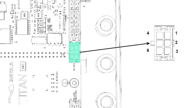
P1: Aux supply connector
Titan GO is self supplied from the DC bus using an internal DC/DC converter that starts at 60 V and works up to 850 V.
However, some applications require an independent auxiliary power supply to work with the power off. This can be done with connector P1.
This connector also includes a +24 V output that can be used for fans, relays or for STO circuits.
P1 connector | ||
|---|---|---|
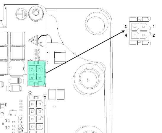 4 pin 2 row Micro-Fit™ 3.0, 3 mm pitch header. Molex | ||
Pin | Signal | Function |
1 | GND_D | Logic ground connection, isolated from GND_P |
| 2 | +24V_IN | +24 V logic supply input (10 V to 60 V) |
| 3 | GND_D | Logic ground connection, isolated from GND_P |
| 4 | +24V_OUT | +24 V logic auxiliar supply output |
Notes | ||
MOLEX Micro-Fit connectors do not follow the typical pinout layout of other connectors such as pin headers or ribbon connectors. Pay close attention not to connect them in a wrong order. | ||
| P1 Mating | |
|---|---|
| Description | 3.00mm Pitch, Micro-Fit™ 3.0 Receptacle Housing, 4 Circuits. |
| Image |
|
| Part number | Molex 43025-0400 |
Distributor code | Digi-Key WM1784-ND / Mouser 538-43025-0400 / Farnell 672890 |
| Notes | |
| |
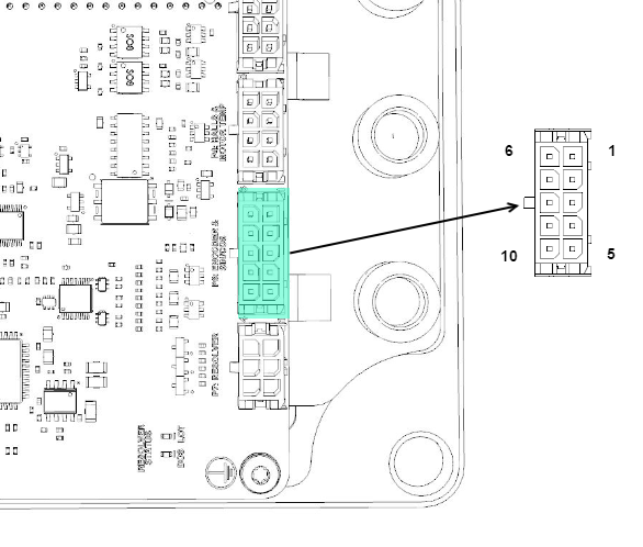
P2: Communications and IOs connector
Titan GO has an isolated connector for the communications and the inputs/outputs. It includes RS-485, CAN, 5x Digital inputs, 1x Digital output and 1x Analog input.
P2 connector | ||
|---|---|---|
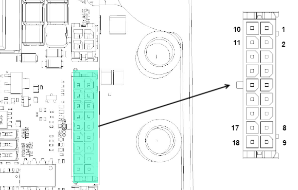 18 pin 2 row Micro-Fit™ 3.0, 3 mm pitch header. | ||
Pin | Signal | Function |
1 | RS485_RX+ | RS485 receive data + (should be connected to master TX+) |
| 2 | RS485_RX- | RS485 receive data - (should be connected to master TX-) |
| 3 | CAN_L | CAN bus line dominant low |
| 4 | CAN_H | CAN bus line dominant high |
| 5 | GND_ISO | Ground for the isolated connector |
| 6 | AN_IN+ | Differential ±10 V analog non inverting input Single ended analog input |
| 7 | GPI2 | General purpose single ended digital input 2 |
| 8 | +5V_ISO | 5 V 50 mA max |
| 9 | GND_ISO | Ground for the isolated connector |
| 10 | RS485_TX+ | RS485 transmit data + (should be connected to master RX+) |
| 11 | RS485_TX- | RS485 transmit data - (should be connected to master RX-) |
| 12 | GND_ISO | Ground for the isolated connector |
| 13 | GPO1 | General purpose digital output |
| 14 | GPI1 | General purpose single ended digital input 1 |
| 15 | AN_IN- | Differential ±10 V analog inverting input Single ended analog input ground |
| 16 | HS_GPI1 | High speed digital single ended input 1 Command source: Pulse input Feedbacks: PWM input |
| 17 | GPI3 | General purpose single ended digital input 3 |
| 18 | HS_GPI2 | High speed digital single ended input 2 Command source: Direction input |
| Notes | ||
| ||
| P2 Mating | |
|---|---|
| Description | 3.00mm Pitch, Micro-Fit™ 3.0 Receptacle Housing, 18 Circuits. |
| Image |
|
| Part number | Molex 43025-0400 |
Distributor code | Digi-Key WM2491-ND / Mouser 538-43025-1800 / Farnell 9961330 |
| Notes | |
| |

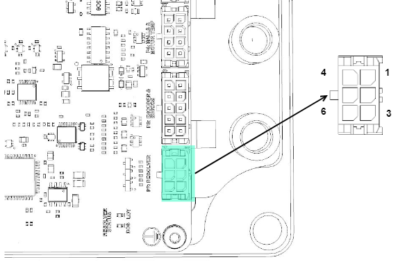
P3: Safe torque off connector
Titan GO has a Safe Torque Off interface (SIL 3 compliant).
P3 connector | ||
|---|---|---|
 6 pin 2 row Micro-Fit™ 3.0, 3 mm pitch header. Molex | ||
Pin | Signal | Function |
1 | STO1 | Safe Torque Off input 1 (24 V levels) |
| 2 | STO2 | Safe Torque Off input 2 (24 V levels) |
| 3 | STO_STATUS_EMITTER | Safe Torque Off Feedback output signalling optocoupler emitter |
| 4 | NC | Not connected |
| 5 | STO_COMMON | Safe Torque Off input common (optocoupler LEDs cathode). |
| 6 | STO_COLLECTOR | Safe Torque Off Feedback output signalling optocoupler collector |
| Notes | ||
| ||
| P3 Mating | |
|---|---|
| Description | 3.00mm Pitch, Micro-Fit™ 3.0 Receptacle Housing, 6 Circuits. |
| Image |
|
| Part number | Molex 43025-0600 |
Distributor code | Digi-Key WM1785-ND / Mouser 538-43025-0600 / Farnell 672907 |
| Notes | |
| |

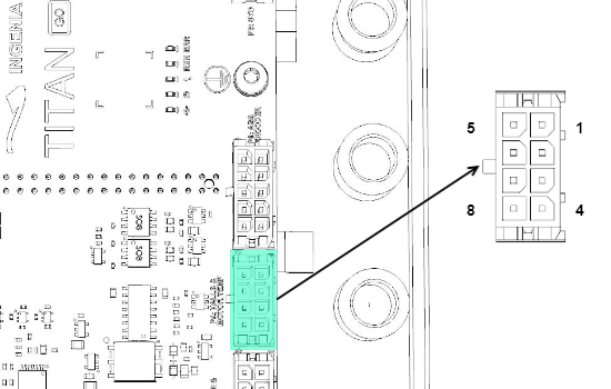
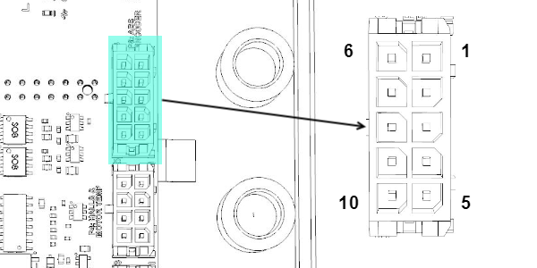
P4: Digital halls and motor temperature connector
P4 connector | ||
|---|---|---|
8 pin 2 row Micro-Fit™ 3.0, 3 mm pitch header. Molex | ||
Pin | Signal | Function |
1 | HALL_1 | Digital Hall 1 sensor input |
| 2 | HALL_2 | Digital Hall 2 sensor input |
| 3 | HALL_3 | Digital Hall 3 sensor input |
| 4 | +5V_OUT | 5 V 50 mA max isolated output for halls |
| 5, 6 | GND_HALLS | Halls only ground connection, isolated from GND_P and GND_D to maximize noise immunity. |
| 7 | MOT_TEMP1 | Motor temperature sensor connection (connect the other terminal to pin 8). Includes a 30 kΩ pull-up to 3.3 V. The pin is connected to analog input 3. |
| 8 | MOT_TEMP2 | Motor temperature sensor return, a 330 Ω connects this pin to digital GND. |
| Notes | ||
| P4 Mating | |
|---|---|
| Description | 3.00mm Pitch, Micro-Fit™ 3.0 Receptacle Housing, 8 Circuits. |
| Image |
|
| Part number | Molex 43025-0800 |
Distributor code | Digi-Key WM1786-ND / Mouser 538-43025-0800 / Farnell 672919 |
| Notes | |
| |

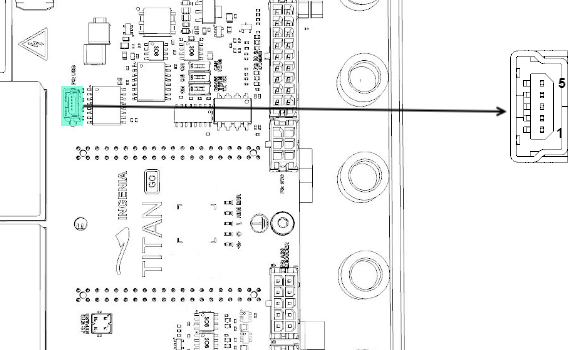
P5: USB connector
P5 connector | ||
|---|---|---|
5 pin vertical mini-USB connector. Wurth Electronics 651005136421. | ||
Pin | Signal | Function |
1 | USB_SUPPLY | USB +5V. Does not supply the Titan. |
| 2 | USB_D+ | USB Data+ line |
| 3 | USB_D- | USB Data- line |
| 4 | NC | Not connected |
| 5 | GND_USB | USB GND, isolated from all other GNDs. |
| SHIELD | NC | Connector metallic shield, NOT CONNECTED. |
| Notes | ||
| ||
| P5 Mating | |
|---|---|
| Description | USB Shielded I/O Cable Assembly, USB A-to-Mini-USB B, 1 m Length, Black, Lead-Free. Not included in the delivery of Titan Go. |
| Image |
|
| Part number | Molex 43025-0800 |
Distributor code | Digi-Key WM17493-ND / Mouser 538-88732-8602 / Farnell 1221071 |

P6: Encoder connector
P6 connector | |||
|---|---|---|---|
10 pin 2 row Micro-Fit™ 3.0, 3 mm pitch header. Molex. | |||
Pin | Signal | Function for incremental encoder | Function for analog encoder (Sin Cos) |
1,3,8 | GND_D | Logic ground. | |
| 2 | QEA/SIN_P | Quadrature A positive input | Sin positive input |
| 4 | QEB/COS_P | Quadrature B positive input | Cos positive input |
| 5 | QEZ/REF_P | Index positive input | Reference positive input |
| 6 | +5V_OUT | 5 V 200 mA regulated and short-circuit protected power supply for the encoder | |
| 7 | QEA/SIN_N | Quadrature A negative input | Sin negative input |
| 9 | QEB/COS_N | Quadrature B negative input | Cos negative input |
| 10 | QEZ/REF_N | Index negative input | Reference negative input |
| Notes | |||
| |||
| P6 Mating | |
|---|---|
| Description | 3.00mm Pitch, Micro-Fit™ 3.0 Receptacle Housing, 10 Circuits. |
| Image |
|
| Part number | Molex 43025-1000 |
Distributor code | Digi-Key WM1787-ND / Mouser 538-43025-1000 / Farnell 672920 |
| Notes | |
| |

P7: Resolver
P7 connector | ||
|---|---|---|
6 pin 2 row Micro-Fit™ 3.0, 3 mm pitch header. Molex. | ||
Pin | Signal | Function for incremental encoder |
1 | EXC+ | Excitation positive |
| 2 | COS+ | Cosine positive |
| 3 | SIN+ | Sine positive |
| 4 | EXC- | Excitation negative |
| 5 | COS- | Cosine negative |
| 6 | SIN- | Sine negative |
| Notes | ||
| ||
| P7 Mating | |
|---|---|
| Description | 3.00mm Pitch, Micro-Fit™ 3.0 Receptacle Housing, 6 Circuits. |
| Image |
|
| Part number | Molex 43025-0600 |
Distributor code | Digi-Key WM1785-ND / Mouser 538-43025-0600 / Farnell 672907 |
| Notes | |
| |
P8: Absolute Encoder
P8 connector | ||
|---|---|---|
6 pin 2 row Micro-Fit™ 3.0, 3 mm pitch header. Molex. | ||
Pin | Signal | Function for absolute encoder |
1 | GND_D | Logic ground. |
| 2 | CLK+ | Clock positive signal output |
| 3 | GND_D | Logic ground. |
| 4 | DIN+ | Data positive signal input |
| 5 | NC | Not connected |
| 6 | +5V_OUT | 5 V 200 mA regulated and short-circuit protected power supply for the encoder |
| 7 | CLK- | Clock negative signal output |
| 8 | GND_D | Logic ground. |
| 9 | DIN- | Data negative signal input |
| 10 | NC | Not connected |
| Notes | ||
This connector was added on version 1.2.0. Wiring is 100% compatible with connectors of version 1.1.0. | ||
| P8 Mating | |
|---|---|
| Description | 3.00mm Pitch, Micro-Fit™ 3.0 Receptacle Housing, 10 Circuits. |
| Image |
|
| Part number | Molex 43025-1000 |
Distributor code | Digi-Key WM1787-ND / Mouser 538-43025-1000 / Farnell 672920 |
| Notes | |
| |