Signalling LEDs
Titan Go Servo Drive provides information through 6 signaling LEDs:
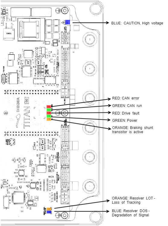
- Supply and operation: 2 LEDs below the Titan Go logo.
- Shunt resistor activation: 1 LED below the Titan Go logo.
- CANopen communication: 2 LEDs below the Titan Go logo.
- High voltage: 1 LED near the AUX Supply connector.
- Resolver Status: 2 LEDs. Near the Resolver connector.
Power and operation signalling LEDs
Three LEDs placed below the Titan Go GO logo indicate the supply and operation status.
LED | Colour | Meaning |
|---|---|---|
POWER | Green | LED is on when internal power supply is working. |
| SHUNT | Orange | LED is turned on when the supply voltage is greater than the maximum voltage configured This signal will only work if the braking resistor output is configured as active. |
FAULT | Red | LED is on when an error event has occurred and the drive is trapped in the Fault state. |
CAN signalling LEDs
Two LEDs below the Titan Go logo provide information about the CANopen communication status, according to CiA 303-3 recommendations. The red LED is ERROR LED and green one is RUN LED.
ERROR LED indicates the status of the CAN physical layer and errors due to missed CAN messages (sync, guard or heartbeat). Next table the meaning of the ERROR LED states:
ERROR LED state* | Concept | Description |
|---|---|---|
Off | No error | Device is in working condition. |
Single flash | Warning limit reached | At least one of the error counters of the CAN controller has reached or |
Double flash | Error control event | A guard event (NMT-slave or NMT-master) or a heartbeat event |
Triple flash | Sync error | The sync message has not been received within the configured |
On | Bus off | The CAN controller is on bus-off condition. |
RUN LED indicates the status of the CANopen network state machine. Next table shows the meaning of the RUN LED states:
RUN LED state* | Concept | Description |
|---|---|---|
Off | Off | The device is switched off |
Blinking | Pre-operational | The device is in state PREOPERATIONAL |
Single flash | Stopped | The device is in state STOPPED |
On | Operational | The device is in state OPERATIONAL |
*See a detailed description of the states in the next table:
* Possible LED states | Description |
|---|---|
ON | The LED is always on |
OFF | The LED is always off |
Single flash | One short flash (~200 ms) followed by a long off phase (~1000 ms) |
Double flash | Sequence of 2 short flashes (~200 ms), separated by an off phase (~200 ms). |
Triple flash | Sequence of 3 short flashes (~200 ms), separated by an off phase (~200 ms). |
Blinking | On and off with a frequency of ~2.5 Hz: ON for ~200 ms followed by off for ~200 ms. |
Note that the specified timings can vary in up to ±20%.
Resolver status LEDs
Resolver LEDs
There are 2 LEDs close to the Resolver feedback connector. If the resolver is functioning correctly both LEDs should be off. They turn on when there is a problem with the Resolver or the Resolver is disconnected.
LED | Colour | Meaning |
|---|---|---|
LOT | Orange | Loss of Tracking. Indicates that it is not possible to follow the resolver angle. |
DOS | Blue | Degradation Of Signal. Indicates that the resolver signal is not well received. Typically when the resolver transformation ratio is not correct or noise is coupled to the lines. |
When no resolver is connected, orange and blue LEDs are on.
Adjusting the resolver
Titan default setting is for a resolver with a transform ratio of 1:0.5. The transform ratio can be adjusted at Ingenia facilities. Please notify the desired resolver specifications when ordering a Titan.
The SIN and COS inputs expect a differential voltage (between positive and negative terminals) of 1.4 VRMS or 3.9 Vpk-pk. However, in some cases, it is possible to adjust the gain by adding a resistor in series with the SIN and COS inputs. This will make a voltage divider with the input differential resistance of 26 kΩ. When the gain is correct, the LOT and DOS LEDs are off.
Resolvers with independent rotor and stator require fine positioning. Ensure perfect collinearity between them and follow the resolver manufacturer instructions.
Both resolver LEDs (LOT and DOS) OFF indicate that the resolver is well positioned and wired.
- Use Ingenia Motion Lab software to set up resolver as the position and/or commutation sensor for the driver. You can use CANopen or the USB port for this purpose.
- With the motor disabled check the position read by the resolver. Rotate the motor and ensure that it's position is well read. Use Ingenia Motion Lab scope with position actual value register being monitored.
- If the orange or blue LEDs are on this means incorrect resolver gain or alignment. Check the correct relative position between stator and rotor of the resolver. Use an oscilloscope to detect the amplitude of sine and cosine (differential) and ensure a sine wave with desired amplitude is observed (peak 3.9Vp-p of sine and cosine at their maximum). Too much amplitude or too low causes a degradation of read signal
Trick: The gain can be changed by sliding the resolver rotor inwards or outwards relative to the stator. (Z axis). This changes the reluctance and affects the transform ratio. - Enable the motor in open loop vector mode, no current loop, no position or velocity loop. Set frequency to 1 Hz or lower and start increasing the voltage gently. Use the motion window in motion lab. Observe that the motor starts moving. Read motor actual current with the scope.
- Check that the resolver position is well-read. If reading errors appear only when the motor is on, this could mean some noise being coupled to the resolver and degrading the signal. Wire the resolver as far as possible from the power cables (to prevent noise coupling). Ensure a good thick and short cable connects the motor housing and the driver PE (Earth) contact. Connecting the motor housing to PE creates a short impedance path for coupled noise and therefore is not coupled to the resolver.
- If the installation allows this to connect the motor housing to the main supply negative (GND). Only do so if an experienced electrician with perfect understanding of the installation and system knows that this is correct.
- When no error appears with motor turning and active (orange and blue leds always off). You can proceed and configure the commutation sensor. After that configure the control loops, starting with the current loop.