Motor and brake
Summit devices can drive a wide variety of actuators. This page describes how the motors are parameterized and how to use additional motor elements such as brake and temperature sensors.
Commutation types
Summit servo drives support different commutation schemes. Following there is the list of possible commutation schemes:
Single-phase commutation
In this type of motors, only phases A and B are controlled. Connecting the motor to phase C will result in unpredictable behavior.
Warning
In this mode, the drive will use the current quadrature command and voltage quadrature command controls only. However, current direct set-point and current direct loop input offset could still affect how some protections are calculated (I2T, derating). Make sure the current direct set-point and current direct loop input offset are both set to 0. Also, the current direct value will always report 0.
Trapezoidal commutation
In this configuration, three phases (A, B and C) are used for control but only two of them are active at a time. Configuration parameters are not needed to start moving this kind of motors, however, a phasing procedure is required to align the commutation with the available feedback.
Warning
In this mode, the drive will use the current quadrature command and voltage quadrature command controls only. However, current direct set-point and current direct loop input offset could still affect how some protections are calculated (I2T, derating). Make sure the current direct set-point and current direct loop input offset are both set to 0. Also, the current direct value will always report 0.
Warning
Trapezoidal modulation can only be used with digital halls as commutation feedback
Sinusoidal commutation (SVPWM)
This commutation is based on the "Field Oriented Control" (FOC) algorithm. In this modulation scheme, the three phases A, B, and C are used for control. Configuration parameters are not needed to start moving this kind of motors, however, a phasing procedure is required to align the commutation with the available feedback.
Go to the Operation section for further information about how to use Summit drives
Motor configuration parameters
Summit servo drives require some information of the driven actuator for protection and operation purpose:
- Motor pole pairs. In combination with the reference and commutation feedbacks allows the drive to compute the electrical angle of the system to commutate properly.
- Rated current. It defines the maximum continuous current that the system is able to drive without being damaged. It is also used to compute the I2T algorithm.
- Peak current. Defines the maximum peak current that the system is able to drive inside a defined window time without being damaged. It is used as an input parameter fo the I2T algorithm.
- Peak current time. Defines the window time of the peak current parameter. It is used as an input parameter fo the I2T algorithm.
Max. current. It defines the maximum current that the system is able to drive without being damaged. This value should be equal to or higher than the peak current.
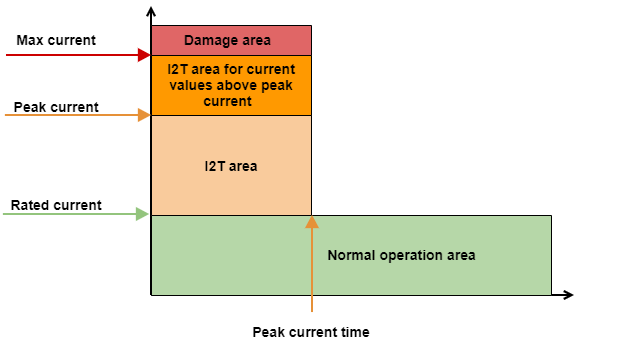
Current values that are higher than peak current but lower than max. current is allowed, however, the peak current time is automatically decreased to respect the I2T defined area. See the Drive protections section for further information.
See Operation section to see further information about how the max current is applied to the drive loops.
Max. velocity. Defines the maximum velocity of the system.
See the Operation section to see further information about how the max velocity is applied to the drive loops.
By default, this protection is always enabled. If the application works in velocity and position based modes, this protection will limit the maximum velocity. On the other hand, in all other modes where the velocity control loop is not available, the protection will stop the motor if the velocity overcomes these limits.
The velocity out of limits protection might be disabled if the application requires it. For further information see the Error management section.
Motor temperature configuration
Different types of temperature sensors are supported for reading motor temperature.
The motor temp. protection threshold parameter indicates the threshold that the drive has to consider for generating a fault if the read temperature overcomes this value.
The motor temp. sensor type indicates which kind of sensor is used for motor temperature readings. The next sensor types are available:
NTC
Involved parameters:
- Resistance. Resistance value for 25 ºC in ohms.
- External resistance. Resistance value in ohms connected to NTC for making the voltage divider.
- Parameter B. B parameter from the NTC datasheet.
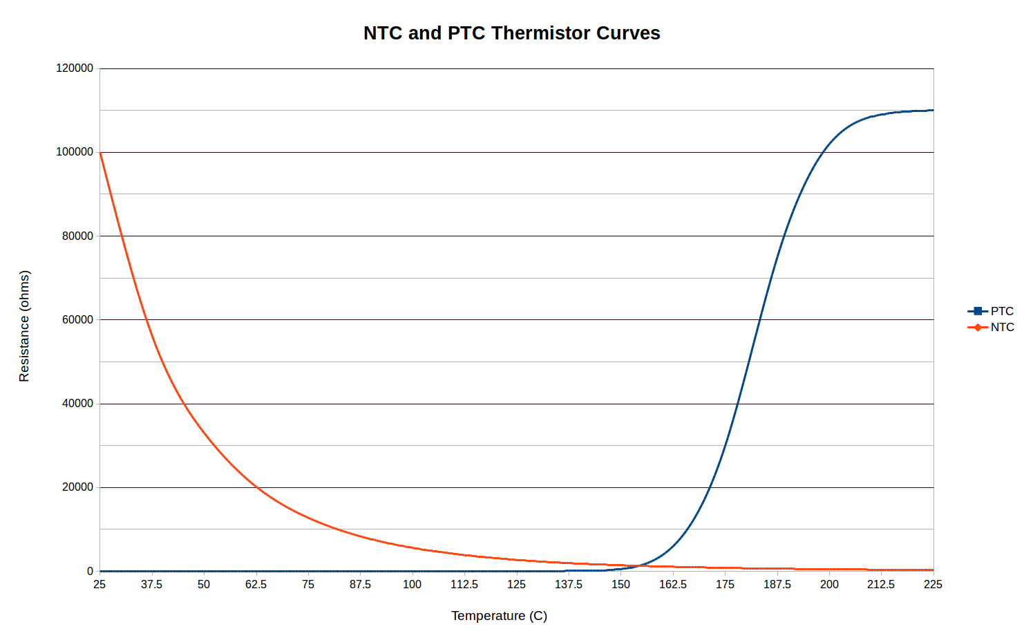
PTC
Involved parameters:
- Resistance. Resistance value in ohms where the over-temperature must be detected.
- External resistance. Resistance value in ohms connected to PTC for making the voltage divider.
- Voltage reference. It contains the voltage applied to the voltage divider.
This mode is not able to read temperatures in the whole range. It only detects if the over-temperature condition exists or not. The motor temperature readings return values of 50.0 ºC if the over-temperature condition is not detected and 125.0 ºC otherwise. However, these values don't represent the real temperature of the motor.
Set motor temperature over-temperature to 100.0 ºC if PTC is used as a motor temperature sensor. As said before, the temperature readings are 50.0 ºC and 125.0 ºC for this configuration and they don't represent the real temperature of the motor. Therefore it is required to set an over-temperature value between 50.0 and 125.0 to force an over-temperature fault reaction, even if this threshold doesn't represent the real over-temperature threshold.
Usually, PTCs are used like an on-off switch temperature sensor. This mode allows configuring the voltage threshold that the drive expects to trigger an over-temperature fault. However, there are PTC sensors with a linear response in a wide range of temperatures. In this case, see the RTD and silicon sensor sections to see how to read the temperature in the whole range.
Linear voltage sensor
Involved parameters:
- Gain. The gain of the sensor, in ºC / V. (From the datasheet)
- Offset. The offset of the sensor, in ºC.
RTD
Involved parameters:
- Temperature 0.Temperature value at one point of the temperature sensor curves.
- Resistance 0. Resistance value at one point in the temperature sensor curves.
- Temperature 1.Temperature value at one point of the temperature sensor curves.
- Resistance 1. Resistance value at one point in the temperature sensor curves.
- External resistance. Pull-up resistance value in ohms connected to the sensor for making the voltage divider.
- Voltage reference. Voltage reference used on temperature sensor electronics (e.g pull-up voltage value).
The measurements of RTD a linearized taking two points of the resistance vs temperature curve/table from the datasheet. To obtain maximum precision for the detection of an over or under temperature condition, choose the points at the same temperature as the condition occurs. Example:
If the under-voltage must be detected at -10 ºC and the over-temperature at 85 ºC, the parameters should be set:
- Temperature 0: -10.0
- Resistance 0: Resistance value at -10 ºC in ohms
- Temperature 1: 85.0
- Resistance 1: Resistance value at 85 ºC in ohms
This sensor type mode compensates automatically the effect of the voltage divider.
Silicon-based sensor
Involved parameters:
- Temperature 0.Temperature value at one point of the temperature sensor curves
- Resistance 0. Resistance value at one point of the temperature sensor curves
- Temperature 1.Temperature value at one point of the temperature sensor curves
- Resistance 1. Resistance value at one point of the temperature sensor curves
- External resistance. Resistance value in ohms connected to the sensor for making the voltage divider
- Voltage reference. Voltage reference used on temperature sensor electronics (e.g pull-up voltage value)
Silicon-based temperature sensors are configured in the same way than RTD.
Switch sensor
Involved parameters:
Voltage reference. Voltage reference used on temperature sensor electronics (e.g pull-up voltage value).
This parameter defines the over-temperature point as voltage reference / 2.We don't have a way to export this macro.
This mode is not able to read temperatures in the whole range. It only detects if the over-temperature condition exists or not. The motor temperature readings return values of 50.0 ºC and 125.0 ºC otherwise. However, these values don't represent the real temperature of the motor.
Set motor temperature over-temperature to 100.0 ºC if switch sensor is used as a motor temperature sensor. As said before, the temperature readings are 50.0 ºC and 125.0 ºC for this configuration and they don't represent the real temperature of the motor. Therefore it is required to set an over-temperature value between 50.0 and 125.0 to force an over-temperature fault reaction, even if this threshold doesn't represent the real over-temperature threshold.
None
Measured temperature values are always 0.0 ºC when this mode is selected.
Brake
Summit servo drives have a dedicated output for controlling an electro-mechanical brake.
This output is automatically managed by the drive following the state machine (CiA402 standard). A PWM modulation might be configured if the brake voltage is higher than the specified. The brake is modulated by a PWM signal. Brake operating mode can be chosen using the register Brake control mode.
Drive only releases the brake in the "operation enable" state.
Brake has implemented two operation modes, voltage and current control mode.
Voltage control mode
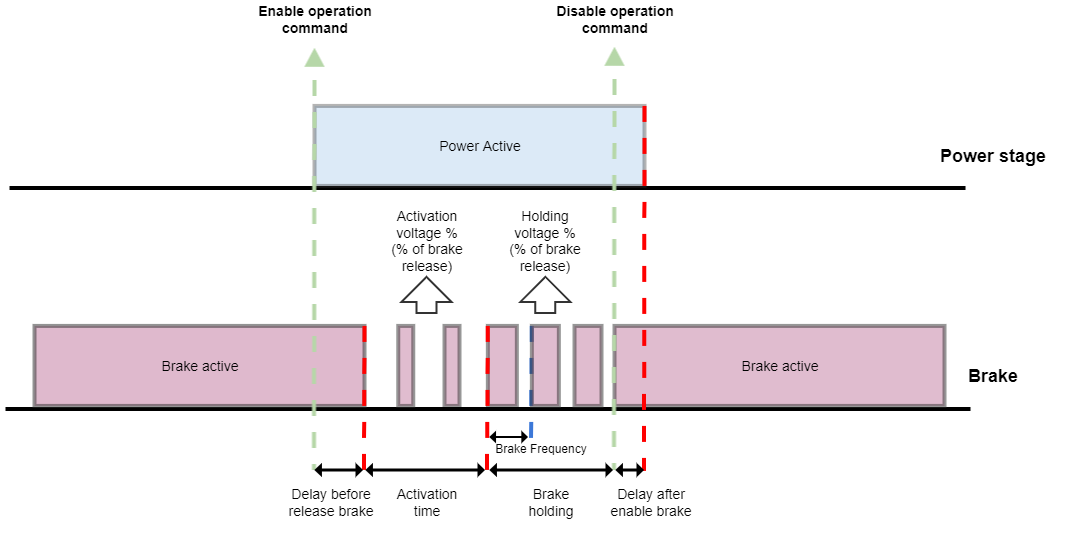
Voltage control mode is useful when the power supply of the brake is stable during all the operation. In this case, the drive will apply a PWM signal at the output pin, with different duty cycles depending on the brake activation stage. The following parameters are used in this operation mode.
- Brake activation voltage percentage. Specifies what effective voltage is applied to release the brake by means of a PWM duty.
- Brake holding voltage percentage. Specifies what effective voltage is applied to hold the brake released by means of a PWM duty.
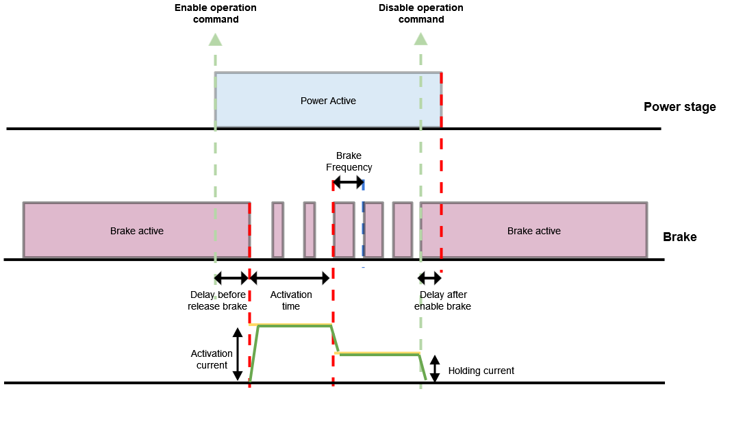
- Delay before release brake. Time delay applied before releasing the brake.
Indicates the delay in milliseconds between activation of the power stage and disengaging the brake (brake activated state). - Delay after enable brake. Time delay applied after enabling the brake.
Indicates the delay in milliseconds between engaging the brake and deactivation of the power stage. - Activation brake time. Time duration in milliseconds of the brake activation stage. If set to 0, the holding stage is directly applied.
Current control mode
Current control mode is useful when the power supply of the brake is not stable and can variate during the operation, the readings from an external current sensor are used by the drive to calculate the required duty cycle to achieve a preset current. In this mode the current applied to the brake is controlled by means of a PI control loop.
Diagram of the brake current control module:
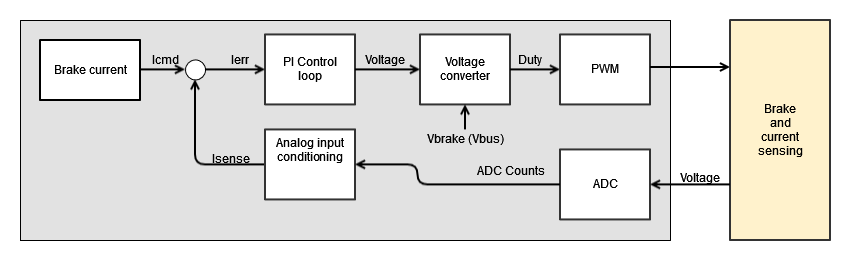
Brake command parameters:
- Brake activation current. Specifies the current applied to release the brake.
- Brake holding current. Specifies the current applied to maintain released the brake.
- Delay before release brake. Time delay applied before releasing the brake.
Indicates the delay in milliseconds between activation of the power stage and disengaging the brake (brake activated state). - Delay after enable brake. Time delay applied after enabling the brake.
Indicates the delay in milliseconds between engaging the brake and deactivation of the power stage. - Activation brake time. Time duration of the brake activation stage. If set to 0, the holding stage is directly applied.
- Brake frequency (Hz). Defines the frequency of the generated PWM signal.
Current control loop parameters:
- Bake Kp and Ki constants. Parameters of the PI for the current adjustment.
- Brake current feedback source. Specifies the analog input used as brake current feedback for closing the control loop.
- Brake max current. Max current allowed on the brake.
Selected analog input must be configured (by means of gain and offset parameters) to provide current in Amperes at the output value.
Brake override
This functionality forces a state in the brake. When the override is disabled, the brake takes the value as dictated by the state machine.
When overriding, the brake can either be locked (no voltage is applied), or released (the activation voltage is applied during activation time, after which the brake is supplied with the holding voltage).
Delay before release brake and delay after enable brake are not used when overriding.
Register brake override should not be written in "operation enable" state.
When changed in "operation enable" state, the behaviour of the drive is unexpected.