Pinout
Connectors Overview
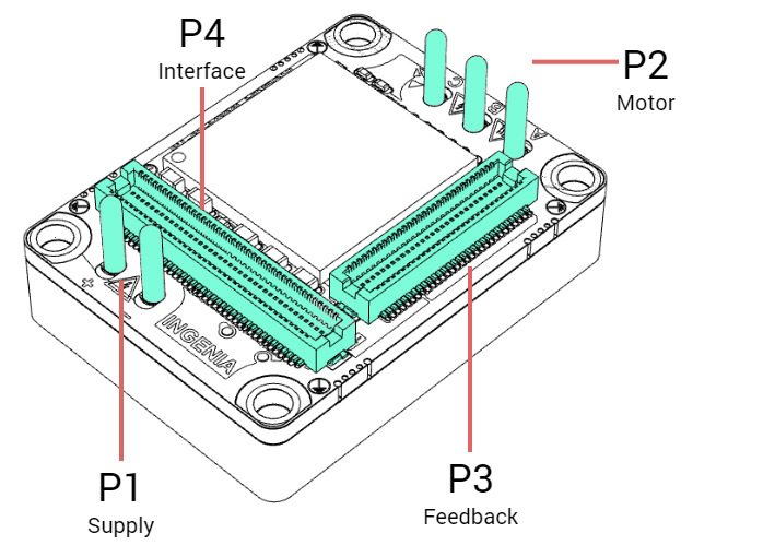
P1 and P2 Power pins
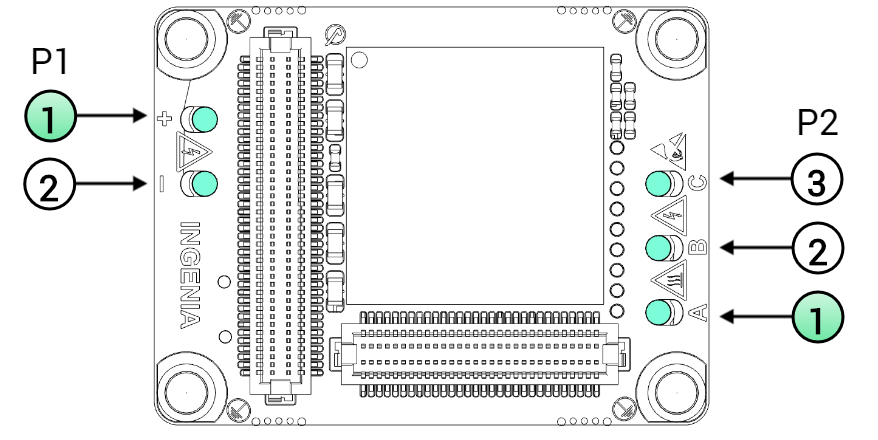
P1 Supply Power pins | ||||
|---|---|---|---|---|
Pin | Name | Type | Function | WARNING, POWER TERMINALS! |
1 | POW_SUP | Power | Power supply positive (DC bus). |
Power pins can have high voltages > 50 V, always respect clearance and creepage requirements (Typ > 0.25 mm)! Dimension PCB traces and connectors according to the current of the application! |
2 | GND_P | Power supply negative (Power Ground). | ||
Chassis | PE | Protective Earth connected to driver housing and fixing M2.5 threads. | Ensure basic insulation (Min > 0.5 mm) between protective earth and other live circuits. | |
P2 Motor Power pins | ||||
|---|---|---|---|---|
Pin | Name | Type | Function | WARNING, POWER TERMINALS! |
1 | PH_A | Power | Motor phase A for 3-phase motors, positive for DC motors. |
Power pins can have high voltages > 50 V, always respect clearance and creepage requirements (Typ > 0.25 mm)! Dimension PCB traces and connectors according to the current of the application! |
2 | PH_B | Motor phase B for 3-phase motors, negative for DC motors. | ||
3 | PH_C | Motor phase C for 3-phase motors (do not connect for DC motors). | ||
Chassis | PE | Protective Earth connected to driver housing and fixing M2.5 threads. | Ensure basic insulation (Min > 0.5 mm) between protective earth and other live circuits. | |
Capitan CORE power pins | Recommended mating contact | Description |
|---|---|---|
Up to 11.2 ARMS rated motors | ||
Ø 1.52 mm, 4 mm pitch, gold plated power pins. | 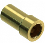 | Beryllium copper TH pin receptacle. Gold plated. PCB hole 2.549 mm. Maximum current 11.2 A. |
Mill-Max 9801-0-15-15-23-27-10-0 | ||
> 11.2 ARMS rated motors | ||
Direct solder to PCB. TH pad with min. hole Ø 1.63 mm. Ensure PCB tracks are wide enough to withstand the target current. | ||
Chassis (aluminum body) | ||
3 mm board-to-board height spacers. | 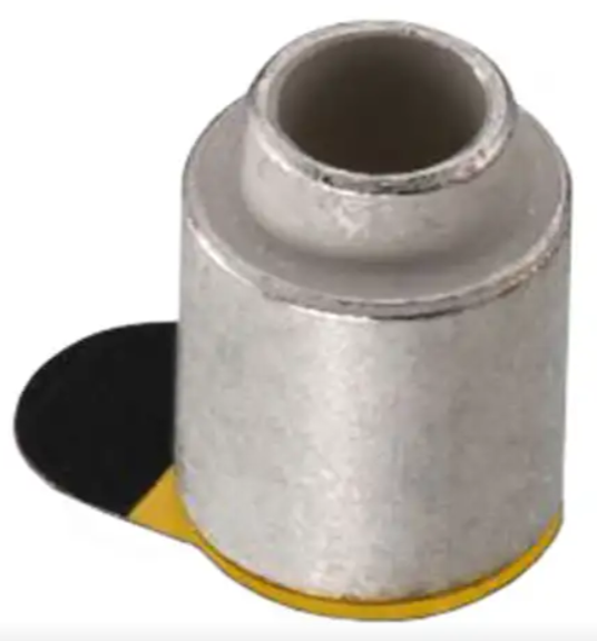 | Surface-mount tinned steel round spacer, Ø 2.7 mm internal, Ø 5.1 mm external, 3 mm board-to-board height. |
Wurth Electronics 9774030951R | ||
 | Unattached nickel-plated brass round spacer, Ø 2.6 mm internal, Ø 4.5 mm external, 3 mm board-to-board height. | |
Ettinger 05.52.033 | ||
P3 Feedback connector
The pinout of the Feedback connector is exactly the same for Capitan CORE (CAP_CORE) and Capitan NET (CAP_NET) although the position of the connector is different.
P3 Feedback connector | |||||||
|---|---|---|---|---|---|---|---|
# | Signal name | Description | Type | # | Signal name | Description | Type |
1 | GND_A | Analog Ground. If no external analog circuits are used, do not connect this pin at all. If used, do not connect this pin to GND_D directly. Instead, use a ferrite bead or 1 Ω resistor in between. | Power | 2 | GND_A | Analog Ground. If no external analog circuits are used, do not connect this pin at all. If used, do not connect this pin to GND_D directly. Instead, use a ferrite bead or 1 Ω resistor in between. | Power |
3 | DNC | Reserved. Do not connect (leave floating). | - | 4 | AN1_P | Analog input 1. Can be used as a command source or for torque sensing. | 16 bit differential analog input |
5 | DNC | 6 | AN1_N | ||||
7 | DNC | 8 | AN2_P | Analog input 2. Can be used as a command source or for torque sensing. | |||
9 | DNC | 10 | AN2_N | ||||
11 | DNC | 12 | DNC | Reserved. Do not connect (leave floating). | - | ||
13 | MOTOR_TEMP | Motor temperature sensor input. 0 V to 5 V level high impedance input. | 12 bit single-ended analog input | 14 | DNC | ||
15 | GND_D | Digital signal Ground. | Power | 16 | NC | Internally not connected. Recommended to leave them unconnected. | |
17 | HALL_1 | Digital hall 1. | Input, 3.3 V level single-ended. | 18 | NC | ||
19 | HALL_2 | Digital hall 2. | 20 | GND_A | Analog Ground. If no external analog circuits are used, do not connect this pin at all. If used, do not connect this pin to GND_D directly. Instead, use a ferrite bead or 1 Ω resistor in between. | Power | |
21 | HALL_3 | Digital hall 3. | 22 | GND_D | Digital signal Ground. | ||
23 | CLL | Reserved. Must be tied or pulled-down to GND_D. | - | 24 | DIG_ENC_1A | Incremental encoder 1 A. | Input, 3.3 V level single-ended. |
25 | CHL | Reserved. Must be tied or pulled-up to 3.3 V. | 26 | DIG_ENC_1B | Incremental encoder 1 B. | ||
27 | CLL | Reserved. Must be tied or pulled-down to GND_D. | 28 | DIG_ENC_1Z | Incremental encoder 1 Index. | ||
29 | CHL | Reserved. Must be tied or pulled-up to 3.3 V. | 30 | DIG_ENC_2A | Incremental encoder 2 A. | ||
31 | DNC | Reserved. Do not connect (leave floating). | 32 | DIG_ENC_2B | Incremental encoder 2 B. | ||
33 | DNC | 34 | DIG_ENC_2Z | Incremental encoder 2 Index. | |||
35 | DNC | 36 | GND_D | Digital signal Ground. | Power | ||
37 | DNC | 38 | ABSENC1_CLK | Clock output for Absolute Encoder 1. | Output | ||
39 | DNC | 40 | ABSENC1_DATA | Data input for Absolute Encoder 1 (supports SSI or up to 2 BiSS-C encoders connected in daisy chain topology). | Input | ||
41 | DNC | 42 | DNC | Reserved. Do not connect (leave floating). | - | ||
43 | DNC | 44 | GND_D | Digital signal Ground. | Power | ||
45 | DNC | 46 | DNC | Reserved. Do not connect (leave floating). | - | ||
47 | DNC | 48 | DNC | ||||
49 | DNC | 50 | DNC | ||||
51 | DNC | 52 | DNC | ||||
53 | DNC | 54 | DNC | ||||
55 | DNC | 56 | DNC | ||||
57 | DNC | 58 | DNC | ||||
59 | GND_D | Digital signal Ground. | Power | 60 | GND_D | Digital signal Ground. | Power |
Notes and naming conventions:
The connector is symmetric, and the polarity does not affect the interface board.
All pins are tolerant to 3.3 V unless otherwise noted.
Unused digital outputs should be left unconnected.
Unused digital inputs should be connected to GND_D.
Unused analog inputs should be connected to 1.65V_REF.
"_P" and "_N" indicates positive and negative terminals of differential signals
"\" Indicates inverted (active low) signal
"NC" means Not Connected. Pins marked with NC can be tied to GND or 3.3 V, but the best practice is to leave them unconnected.
"DNC" means Do Not Connect. Pins marked with DNC must not be tied to any driving voltage, including GND or 3.3 V.
"CLL" means Connect to Low Level. Pins marked with CLL must be tied or pulled-down to 0 V.
"CHL" means Connect to High Level. Pins marked with CHL must be tied or pulled-up to 3.3 V.
Manufacturer | Capitan CORE connector | Required mating connector | Description |
|---|---|---|---|
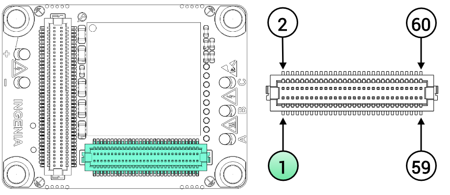
Hirose Electric | 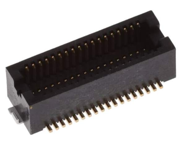 | 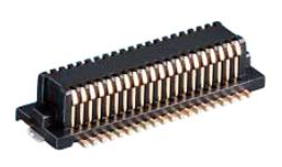 | 60-pin mezzanine stacking board connector. 0.5 mm pitch. Center strip, gold-plated surface mount contacts. 3 mm stacking height. Hirose DF12 connectors operation and storage temperature, when mounted, is -45 ºC to 125 ºC. |
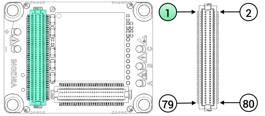
P4 Capitan CORE Interface connector
Although using the same physical connector as Capitan NET (CAP-NET), position and pinout are different in Capitan CORE (CAP-CORE).
P4 Capitan CORE Interface connector | |||||||
|---|---|---|---|---|---|---|---|
# | Signal name | Description | Type | # | Signal name | Description | Type |
1 | GND_D | Digital signal Ground. | Power | 2 | GND_D | Digital signal Ground. | Power |
3 | 5V_D | 5 V, 300 mA continuous logic supply input. Must be low ripple and ensure ±2% regulation tolerance or less. It is advised to connect all four 5V_D pins. It is recommended to provide at least 500 mA input current if pins 9 or 10 (3.3V_D) are used to drive external circuits. The rise time of the 5 V supply must be between 2 ms and 10 ms to guarantee a proper initialization. | Power input | 4 | 5V_D | 5 V, 300 mA continuous logic supply input. Must be low ripple and ensure ±2% regulation tolerance or less. It is recommended to connect all four 5V_D pins. It is advised to provide at least 500 mA input current if pins 9 or 10 (3.3V_D) are used to drive external circuits. The rise time of the 5 V supply must be between 2 ms and 10 ms to guarantee a proper initialization. | Power input |
5 | 5V_D | 6 | 5V_D | ||||
7 | GND_D | Digital signal Ground. | Power | 8 | GND_D | Digital signal Ground. | Power |
9 | 3.3V_D | 3.3 V, 250 mA max. output to supply peripherals. Excessive current demand on this pin could cause failure or even permanent damage to the Capitan CORE. | Power output | 10 | 3.3V_D | 3.3 V, 250 mA max. output to supply peripherals. Excessive current demand on this pin could cause failure or even permanent damage to the Capitan CORE. | Power output |
11 | GND_D | Digital signal Ground. | Power | 12 | GND_D | Digital signal Ground. | Power |
13 | GND_D | 14 | MCB_SPI_MISO | Motion Control Bus, Master input Slave output | Output | ||
15 | GND_D | 16 | MCB_SPI_MOSI | Motion Control Bus, Master output Slave input | Input | ||
17 | GND_D | 18 | \MCB_SPI_CS | Motion Control Bus, Chip Select input | |||
19 | GND_D | 20 | MCB_SPI_CLK | Motion Control Bus, Clock input | |||
21 | GND_D | 22 | MCB_SYNC0 | Motion Control Bus, synchronization signal 0 | |||
23 | GND_D | 24 | MCB_SYNC1 | Motion Control Bus, synchronization signal 1. It is strongly suggested to pull-up this signal to 3.3V with a 10 kΩ resistor. | Output | ||
25 | GND_D | 26 | MCB_IRQ | Motion Control Bus, interrupt request output. Add a pull-down resistor 10 kΩ to this pin. | |||
27 | GND_D | 28 | DNC | Reserved. Do not connect (leave floating). | - | ||
29 | NC | Internally not connected. Recommended to leave them unconnected. | - | 30 | GND_D | Digital signal Ground. | Power |
31 | NC | 32 | GND_D | ||||
33 | \STO1 | Safe Torque Off input 1 (non-isolated). Both \STO1 and \STO2 must be high-level (3.3 V and 5 V level compatible) to allow operation of the motor. Holding different logic states (STO1 ≠ STO2) for more than 1s will cause a latching fault. | Input | 34 | \STO2 | Safe Torque Off input 2 (non-isolated). Both \STO1 and \STO2 must be high-level (3.3 V and 5 V level compatible) to allow operation of the motor. Holding different logic states (STO1 ≠ STO2) for more than 1s will cause a latching fault. | Input |
35 | DNC | Reserved. Do not connect (leave floating). | - | 36 | DNC | Reserved. Do not connect (leave floating). | - |
37 | FAULT_SIGNAL | Fault state signaling output. Can directly drive a (typically) red LED anode at 3.3 V up to 3 mA. | Output | 38 | \HW_RESET | Capitan CORE reset input. Keeps the motion controller disabled with low power consumption. A minimum low-level pulse of 100 µs is needed for resetting Capitan CORE. 2 kΩ pull-up to 3.3 V is internally included. | Input |
39 | GND_D | Digital signal Ground. | Power | 40 | DNC | Reserved. Do not connect (leave floating). | - |
41 | \EXT_FAULT | External fault input. Could be configured to force the Capitan CORE state-machine to the Fault state (motor will be stopped) when the pin is driven to 0 V. Includes an internal weak pull-up, although external pull-up to 3.3 V is advised. | Input | 42 | PWM_BRAKE | PWM output for driving a mechanical brake. Configurable up to 40 kHz. A high level indicates the motor is free to move. Add a 10 kΩ ~ 47 kΩ pull-down resistor to this pin to ensure the brake is always in a safe state during boot-up or reset situations when this pin might be in high impedance. | Output |
43 | GPO4 | Digital Output 4. | Output | 44 | DNC | Reserved. Do not connect (leave floating). | - |
45 | DNC | Reserved. Do not connect (leave floating). | - | 46 | DNC | ||
47 | GPI1 | Digital Input 1. | Input | 48 | DNC | ||
49 | GPI2 | Digital Input 2. | 50 | ABSENC2_CLK | Clock output for Absolute Encoder 2. | Output | |
51 | ABSENC2_DATA | Data input for Absolute Encoder 2 (supports SSI only) | 52 | DNC | Reserved. Do not connect (leave floating). | - | |
53 | GPI3 | Digital Input 3. | 54 | DNC | |||
55 | GPO1 | Digital Output 1. | Output | 56 | GPO2 | Digital Output 2. | Output |
57 | GPO3 | Digital Output 3. | 58 | GPI4 | Digital Input 4. | Input | |
59 | GND_D | Digital signal Ground. | Power | 60 | GND_D | Digital signal Ground. | Power |
61 | DNC | Reserved. Do not connect (leave floating). | - | 62 | DNC | Reserved. Do not connect (leave floating). | - |
63 | DNC | 64 | DNC | ||||
65 | DNC | 66 | DNC | ||||
67 | GND_D | Digital signal Ground. | Power | 68 | GND_D | Digital signal Ground. | Power |
69 | NC | Internally not connected. Recommended to leave them unconnected. | - | 70 | NC | Internally not connected. Recommended to leave them unconnected. | - |
71 | NC | 72 | NC | ||||
73 | NC | 74 | NC | ||||
75 | 1.65V_REF | 1.65 V voltage reference output with sink/source capability up to ±10 mA. Excessive current demand or noise coupled to this pin can cause a loss of performance or even malfunction of Capitan CORE: route by following the best layout practices. | Power output | 76 | NC | ||
77 | 3.3V_REF | 3.3 V voltage reference output with sink/source capability up to ±10 mA. Excessive current demand or noise coupled to this pin can cause a loss of performance or even malfunction of Capitan CORE: route by following the best layout practices. | 78 | DNC | Reserved. Do not connect (leave floating). | ||
79 | GND_A | Analog Ground. If no external analog circuits are used, do not connect this pin at all. If used, do not connect this pin to GND_D directly. Instead, use a ferrite bead or 1 Ω resistor in between. | Power | 80 | GND_A | Analog Ground. If no external analog circuits are used, do not connect this pin at all. If used, do not connect this pin to GND_D directly. Instead, use a ferrite bead or 1 Ω resistor in between. | Power |
Notes and naming conventions:
The connector is symmetric, and the polarity does not affect the interface board.
All pins are tolerant to 3.3 V unless otherwise noted.
Unused digital outputs should be left unconnected.
Unused digital inputs should be connected to GND_D.
Unused analog inputs should be connected to 1.65V_REF.
"_P" and "_N" indicates positive and negative terminals of differential signals
"\" Indicates inverted (active low) signal
"NC" means Not Connected. Pins marked with NC can be tied to GND or 3.3 V, but the best practice is to leave them unconnected.
"DNC" means Do Not Connect. Pins marked with DNC must not be tied to any driving voltage, including GND or 3.3 V.
Motion Control Bus
Capitan CORE can be controlled as a slave by means of its proprietary Motion Control Bus (MCB). Check how in the Summit Series Reference Manual.
MCB Layout is critical
Note, the high-speed MCB signals (MCB_SPI_MOSI, MCB_SPI_MISO, MCB_SPI_CLK) must be routed with care. Not following the best high speed layout practices will result in communication problems and loss of data. Please:
Do not ever route these signals close to the motor phases or switching nodes of DC/DCs. Keep a safe > 15 mm distance to switching noise.
Ensure they have a good GND return on all its length on the PCB. Route them as strip lines, if possible microstrip for longer distances is also recommended.
Keep line impedances between 60 Ω and 150 Ω.
Avoid T stubs and acute angles.
Minimize crosstalk to other signals by reducing parallel coupled length.
Consider adding 0 Ω ~ 47 Ω series termination resistors at the end of the fast lines as a provision to minimize reflections in case communication issues arise.
Manufacturer | Capitan CORE connector | Required mating connector | Description |
|---|---|---|---|
Hirose Electric | 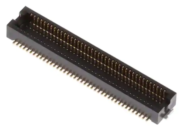 | 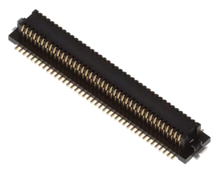 | 80-pin mezzanine stacking board connector. 0.5 mm pitch. Center strip, gold-plated surface mount contacts. 3 mm stacking height. Hirose DF12 connectors operation and storage temperature, when mounted, is -45ºC to 125ºC. |