Pinout
Connectors Overview
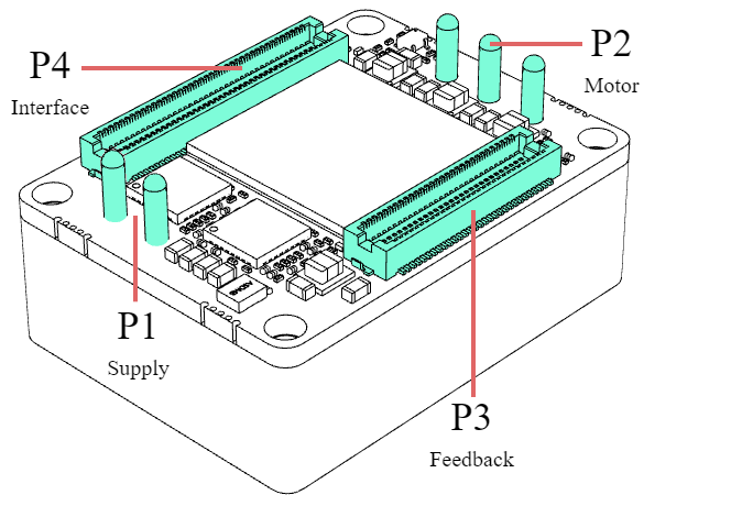
P1 and P2 Power pins
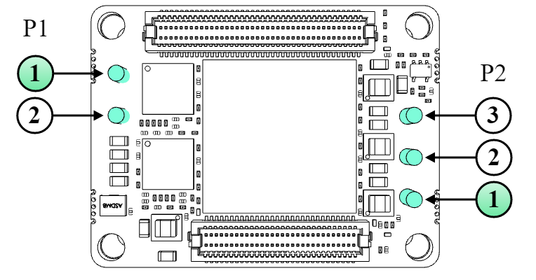
| P1 Supply Power pins | ||||
|---|---|---|---|---|
| Pin | Name | Type | Function | WARNING, POWER TERMINALS! |
| 1 | POW_SUP | Power | Power supply positive (DC bus). |
Power pins can have high voltages > 50 V, always respect clearance and creepage requirements (Typ > 0.25 mm)! Dimension PCB traces and connectors according to the current of the application! |
| 2 | GND_P | Power supply negative (Power Ground). Internally connected to GND_D on a single point. | ||
| Chassis | PE | Protective Earth connected to driver housing and fixing M2.5 threads. | Ensure basic insulation (Min > 0.5 mm) between protective earth and other live circuits. | |
| P2 Motor Power pins | ||||
|---|---|---|---|---|
| Pin | Name | Type | Function | WARNING, POWER TERMINALS! |
| 1 | PH_A | Power | Motor phase A for 3-phase motors, positive for DC motors. |
Power pins can have high voltages > 50 V, always respect clearance and creepage requirements (Typ > 0.25 mm)! Dimension PCB traces and connectors according to the current of the application! |
| 2 | PH_B | Motor phase B for 3-phase motors, negative for DC motors. | ||
| 3 | PH_C | Motor phase C for 3-phase motors (do not connect for DC motors). | ||
| Chassis | PE | Protective Earth connected to driver housing and fixing M2.5 threads. | Ensure basic insulation (Min > 0.5 mm) between protective earth and other live circuits. | |
| Everest NET power pins | Recommended mating contact | Description |
|---|---|---|
| Up to 11.2 ARMS rated motors | ||
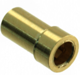
Ø 1.52 mm, 4 mm pitch, gold plated power pins. |
| Beryllium copper TH pin receptacle. Gold plated. PCB hole 2.549 mm. Maximum current 11.2 A. |
| Mill-Max 9801-0-15-15-23-27-10-0 | ||
| > 11.2 A rated motors | ||
| Direct solder to PCB. TH pad with min. hole Ø 1.63 mm. Ensure PCB tracks are wide enough to withstand the target current. | ||
| Chassis (aluminum body) | ||
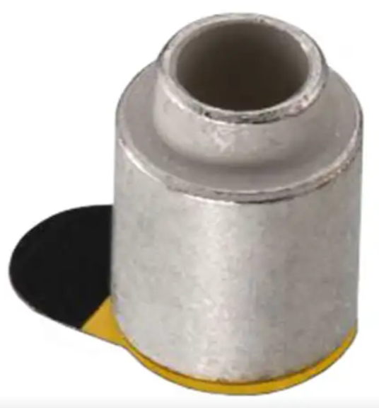
| 3 mm board-to-board height spacers. |
| Surface-mount tinned steel round spacer, Ø 2.7 mm internal, Ø 5.1 mm external, 3 mm board-to-board height. |
| Wurth Electronics 9774030951R | ||
P3 Feedback connector
The pinout of the Feedback connector is exactly the same for Everest NET (EVE_NET) and Everest CORE (EVE_CORE) although the position of the connector is different.
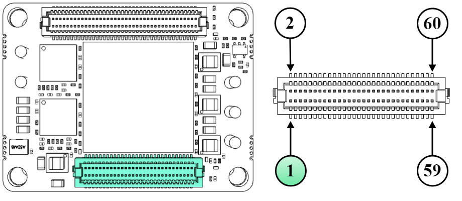
| P3 Feedback connector | |||||||
|---|---|---|---|---|---|---|---|
# | Signal name | Description | Type | # | Signal name | Description | Type |
1 | GND_A | Analog Ground. If no external analog circuits are used, do not connect this pin at all. If used, do not connect this pin to GND_D directly. Instead, use a ferrite bead or 1 Ω resistor in between. | Power | 2 | GND_A | Analog Ground. If no external analog circuits are used, do not connect this pin at all. If used, do not connect this pin to GND_D directly. Instead, use a ferrite bead or 1 Ω resistor in between. | Power |
3 | DNC | Reserved. Do not connect (leave floating). | - | 4 | AN1_P | Analog input 1. Can be used for torque sensing. | 16 bit differential analog input |
5 | DNC | 6 | AN1_N | ||||
7 | DNC | 8 | AN2_P | Analog input 2. Can be used for torque sensing. | |||
9 | DNC | 10 | AN2_N | ||||
11 | DNC | 12 | DNC | Reserved. Do not connect (leave floating). | - | ||
13 | MOTOR_TEMP | Motor temperature sensor input. 0 V to 5 V level high impedance input. | 12-bit single-ended analog input | 14 | DNC | ||
15 | GND_D | Digital signal Ground. | Power | 16 | NC | Internally not connected. Recommended to leave them unconnected. | |
17 | HALL_1 | Digital hall 1. | Single-ended 3.3 V inputs. | 18 | NC | ||
19 | HALL_2 | Digital hall 2. | 20 | GND_A | Analog Ground. If no external analog circuits are used, do not connect this pin at all. If used, do not connect this pin to GND_D directly. Instead, use a ferrite bead or 1 Ω resistor in between. | Power | |
21 | HALL_3 | Digital hall 3. | 22 | GND_D | Digital signal Ground. | ||
23 | CLL | Reserved. Must be tied or pulled-down to GND_D. | - | 24 | DIG_ENC_1A | Incremental encoder 1 A. | Single-ended 3.3 V inputs. |
25 | CHL | Reserved. Must be tied or pulled-up to 3.3 V. | 26 | DIG_ENC_1B | Incremental encoder 1 B. | ||
27 | CLL | Reserved. Must be tied or pulled-down to GND_D. | 28 | DIG_ENC_1Z | Incremental encoder 1 Index. | ||
29 | CHL | Reserved. Must be tied or pulled-up to 3.3 V. | 30 | DIG_ENC_2A | Incremental encoder 2 A. | ||
31 | DNC | Reserved. Do not connect (leave floating). | 32 | DIG_ENC_2B | Incremental encoder 2 B. | ||
33 | DNC | 34 | DIG_ENC_2Z | Incremental encoder 2 Index. | |||
35 | DNC | 36 | GND_D | Digital signal Ground. | Power | ||
37 | DNC | 38 | ABSENC1_CLK | Clock output for Absolute Encoder 1. | Output | ||
39 | DNC | 40 | ABSENC1_DATA | Data input for Absolute Encoder 1 (supports SSI or up to 2 BiSS-C encoders connected in daisy chain topology). | Input | ||
41 | DNC | 42 | DNC | Reserved. Do not connect (leave floating). | - | ||
43 | DNC | 44 | GND_D | Digital signal Ground. | Power | ||
45 | DNC | 46 | DNC | Reserved. Do not connect (leave floating). | - | ||
47 | DNC | 48 | DNC | ||||
49 | DNC | 50 | DNC | ||||
51 | DNC | 52 | DNC | ||||
53 | DNC | 54 | DNC | ||||
55 | DNC | 56 | DNC | ||||
57 | DNC | 58 | DNC | ||||
59 | GND_D | Digital signal Ground. | Power | 60 | GND_D | Digital signal Ground. | Power |
Notes and naming conventions:
- All pins are tolerant to 3.3 V unless otherwise noted.
- Unused digital outputs should be left unconnected.
- Unused digital inputs should be connected to GND_D if not specified otherwise.
- Unused analog inputs should be connected to 1.65V_REF.
- "_P" and "_N" suffixes indicate positive and negative terminals of differential signals.
- "\" Indicates inverted (active low) signal.
- "NC" means Not Connected. Pins marked with NC can be tied to GND or 3.3 V, but the best practice is to leave them unconnected.
- "DNC" means Do Not Connect. Pins marked with DNC must not be tied to any driving voltage, including GND or 3.3 V.
- "CLL" means Connect to Low Level. Pins marked with CLL must be tied or pulled-down to 0 V.
- "CHL" means Connect to High Level. Pins marked with CHL must be tied or pulled-up to 3.3 V.
| Manufacturer | Everest NET connector | Required mating connector | Description |
|---|---|---|---|
| Hirose Electric |
|
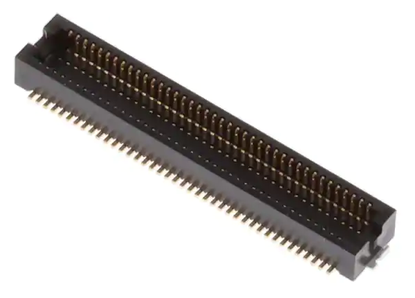
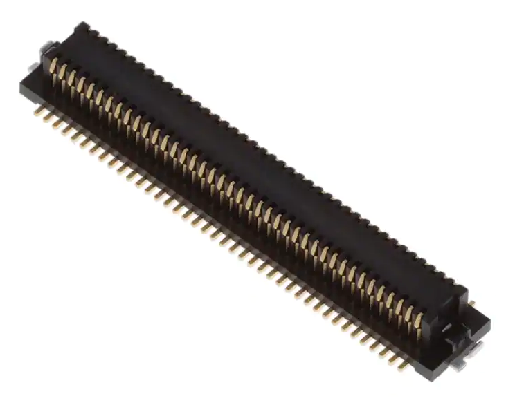
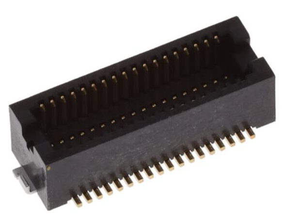
| 60-pin mezzanine stacking board connector. 0.5 mm pitch. Center strip, gold-plated surface mount contacts. 3 mm stacking height. Hirose DF12 connectors operation and storage temperature, when mounted, is -45ºC to 125ºC. |
| DF12NB(3.0)-60DP-0.5V(51) | DF12NB(3.0)-60DS-0.5V(51) |
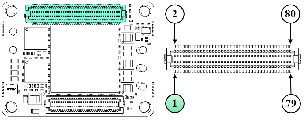
P4 Everest NET Interface connector
Although using the same physical connector as Everest CORE (EVE-CORE), position and pinout are different in Everest NET (EVE-NET).
| P4 Everest NET Interface connector | |||||||
|---|---|---|---|---|---|---|---|
| # | Signal name | Description | Type | # | Signal name | Description | Type |
| 1 | 3.3V_REF | 3.3 V voltage reference output with sink/source capability up to ±10 mA. Excessive current demand or noise coupled to this pin can cause a loss of performance or even malfunction of Everest NET: route by following the best layout practices. | Power output | 2 | DNC | Reserved. Do not connect (leave floating). | - |
| 3 | GND_A | Analog Ground. If no external analog circuits are used, do not connect this pin at all. If used, do not connect this pin to GND_D directly. Instead, use a ferrite bead or 1 Ω resistor in between. | Power | 4 | 1.65V_REF | 1.65 V voltage reference output with sink/source capability up to ±10 mA. Excessive current demand or noise coupled to this pin can cause a loss of performance or even malfunction of Everest NET: route by following the best layout practices. | Power output |
| 5 | GND_D | Digital signal Ground. | 6 | GND_D | Digital signal Ground. | Power | |
| 7 | 5V_D | 5 V, 1 A continuous logic supply input. Must be low ripple and ensure ±2% regulation tolerance or less. All four 5V_D pins must be connected. It is advised to provide at least 1.2 A input current if pins 13 or 14 (3.3V_D) are used to drive external circuits. The rise time of the 5 V supply must be between 2 ms and 10 ms to guarantee a proper initialization. | Power input | 8 | 5V_D | 5 V, 1 A continuous logic supply input. Must be low ripple and ensure ±2% regulation tolerance or less. All four 5V_D pins must be connected. It is advised to provide at least 1.2 A input current if pins 13 or 14 (3.3V_D) are used to drive external circuits. The rise time of the 5 V supply must be between 2 ms and 10 ms to guarantee a proper initialization. | Power input |
| 9 | 5V_D | 10 | 5V_D | ||||
| 11 | GND_D | Digital signal Ground. | Power | 12 | GND_D | Digital signal Ground. | Power |
| 13 | MAGNETICS_CT | 3.3 V dedicated voltage output for the EtherCAT magnetics center tap. Do not connect this pin to another voltage source or load other than the center tap of the EtherCAT transformers. Do not connect to pin 14. | Power output | 14 | 3.3V_D | 3.3 V, 250 mA max. output to supply peripherals. Excessive current demand on this pin could cause failure or even permanent damage to the Everest NET. | Power output |
| 15 | GND_D | Digital signal Ground. | Power | 16 | GND_D | Digital signal Ground. | Power |
| 17 | GPO4 | Digital Output 4. | Output | 18 | GPI1 | Digital Input 1. | Input |
| 19 | GPI2 | Digital Input 2. | Input | 20 | GPI3 | Digital Input 3. | |
| 21 | DNC | Reserved. Do not connect (leave floating). | - | 22 | DNC | Reserved. Do not connect (leave floating). | - |
| 23 | DNC | 24 | ABSENC2_CLK | Clock output for Absolute Encoder 2. | Output | ||
| 25 | ABSENC2_DATA | Data input for Absolute Encoder 2 (supports SSI only) | Input | 26 | DNC | Reserved. Do not connect (leave floating). | - |
| 27 | DNC | Reserved. Do not connect (leave floating). | - | 28 | DNC | ||
| 29 | GPO1 | Digital Output 1. | Output | 30 | GPO2 | Digital Output 2. | Output |
| 31 | GPO3 | Digital Output 3. | 32 | GPI4 | Digital Input 4. | Input | |
| 33 | \STO1 | Safe Torque Off input 1 (non-isolated). Both \STO1 and \STO2 must be high-level (3.3 V and 5 V level compatible) to allow operation of the motor. Holding different logic states (STO1 ≠ STO2) for more than 1s will cause a latching fault. | Input | 34 | \STO2 | Safe Torque Off input 2 (non-isolated). Both \STO1 and \STO2 must be high-level (3.3 V and 5 V level compatible) to allow operation of the motor. Holding different logic states (STO1 ≠ STO2) for more than 1s will cause a latching fault. | |
| 35 | GND_D | Digital signal Ground. | Power | 36 | FAULT_SIGNAL | Fault state signaling output. Can directly drive a (typically) red LED anode at 3.3 V up to 3 mA. | Output |
| 37 | DNC | Reserved. Do not connect (leave floating). | - | 38 | GND_D | Digital signal Ground. | Power |
| 39 | DNC | 40 | DNC | Reserved. Do not connect (leave floating). | - | ||
| 41 | PWM_BRAKE | PWM output for driving a mechanical brake. Configurable up to 40 kHz. A high level indicates the motor is free to move. Add a 10 kΩ ~ 47 kΩ pull-down resistor to this pin to ensure the brake is always in a safe state during boot-up or reset situations when this pin might be in high impedance. | Output | 42 | DNC | ||
| 43 | DNC | Reserved. Do not connect (leave floating). | - | 44 | DNC | ||
| 45 | DNC | 46 | GND_D | Digital signal Ground. | Power | ||
| 47 | DNC | 48 | DNC | Reserved. Do not connect (leave floating). | - | ||
| 49 | DNC | 50 | DNC | ||||
| 51 | \BOOT or DNC | This pin can be pulled down to GND_D to force enter boot mode during power-up in FTP mode. Typically not necessary. If not used, always leave unconnected or pulled up with a 10 kΩ resistor. Never leave this pin permanently pulled down, as this would block the Everest in boot mode. | I/O | 52 | DNC | ||
| 53 | DNC | Reserved. Do not connect (leave floating). | - | 54 | DNC | ||
| 55 | CAN_TX | 3.3 V TTL-levels Transmit pin of CAN data frame. Requires an external transceiver to shift into CAN physical layer. | Output | 56 | DNC | ||
| 57 | CAN_RX | 3.3 V TTL-levels Receive pin of CAN data frame. Requires an external transceiver to shift into CAN physical layer. If not used pull-up high. Do not leave unconnected. | Input | 58 | DNC | ||
| 59 | GND_D | Digital signal Ground. | Power | 60 | GND_D | Digital signal Ground. | Power |
| 61 | DNC | Reserved. Do not connect (leave floating). | - | 62 | DNC | Reserved. Do not connect (leave floating). | - |
| 63 | DNC | 64 | ECAT_CAN_ERR | State machine ERROR red LED for EtherCAT and CANopen. Can directly drive a red LED anode at 3.3 V up to 3 mA. | Output | ||
| 65 | ECAT_CAN_RUN | State-machine RUN green LED output for EtherCAT and CANopen. Can directly drive a green LED anode at 3.3 V up to 3 mA. | Output | 66 | DNC | Reserved. Do not connect (leave floating). | - |
| 67 | \ETH0_LED_LINK | Ethernet Port 0 Link signaling. Must be connected to high impedance or be buffered to drive a (typically) green LED. Use an inverting buffer to drive the LED anode or an open collector element to sink the cathode current. | 68 | \ETH1_LED_LINK | Ethernet Port 1 Link signaling. Must be connected to high impedance or be buffered to drive a (typically) green LED. Use an inverting buffer to drive the LED anode or an open collector element to sink the cathode current. | Output | |
| 69 | GND_D | Digital signal Ground. | Power | 70 | GND_D | Digital signal Ground. | Power |
| 71 | PHY0_TX_P | Port 0 Ethernet physical layer differential pairs. 50 Ω pull-up termination resistors are included on the drive. Magnetics with the center tap connected to MAGNETICS_CT (pin 13) must be added externally. If this port is not used leave these pins unconnected. | I/O | 72 | PHY1_TX_P | Port 1 Ethernet physical layer differential pairs. 50 Ω pull-up termination resistors are included on the drive. Magnetics with the center tap connected to MAGNETICS_CT (pin 13) must be added externally. If this port is not used leave these pins unconnected. | I/O |
| 73 | PHY0_TX_N | 74 | PHY1_TX_N | ||||
| 75 | PHY0_RX_P | 76 | PHY1_RX_P | ||||
| 77 | PHY0_RX_N | 78 | PHY1_RX_N | ||||
| 79 | GND_D | Digital signal Ground. | Power | 80 | GND_D | Digital signal Ground. | Power |
Notes and naming conventions:
- All pins are tolerant to 3.3 V unless otherwise noted.
- Unused digital outputs should be left unconnected.
- Unused digital inputs should be connected to GND_D if not specified otherwise.
- Unused analog inputs should be connected to 1.65V_REF.
- "_P" and "_N" indicate positive and negative terminals of differential signals.
- "\" Indicates inverted (active low) signal.
- "NC" means Not Connected. Pins marked with NC can be tied to GND or 3.3 V, but the best practice is to leave them unconnected.
- "DNC" means Do Not Connect. Pins marked with DNC must not be tied to any driving voltage, including GND or 3.3 V.
| Manufacturer | Everest NET connector | Required mating connector | Description |
|---|---|---|---|
| Hirose Electric |
|
| 80-pin mezzanine stacking board connector. 0.5 mm pitch. Center strip, gold-plated surface mount contacts. 3 mm stacking height. Hirose DF12 connectors operation and storage temperature, when mounted, is -45ºC to 125ºC. |
| DF12NB(3.0)-80DP-0.5V(51) | DF12NB(3.0)-80DS-0.5V(51) |