Current modes (CSC, C, CA)
Summit devices implement different ways to use current loop control to adapt the needs to the application:
Current (C). Current mode in q-d axis.
Cyclic synchronous current (CSC). Current mode in q-d axis using an internal interpolator.
Current amplifier (CA). Current mode in a-b-c axis.
Current (C) and Cyclic Synchronous Current (CSC) modes
This mode is used to command the current driven through the actuator. It requires a proper configuration of the commutation sensor.
The commutation sensor configuration process is described in the Commutation section.
If software position limits are enabled using this mode of operation, the drive will generate a fault if the position limits are exceeded. Set them to 0 to disable this functionality
If actuator velocity overcomes the max. velocity parameter using this mode of operation, the drive will generate a fault. Disable the fault generation masking it.
Control scheme
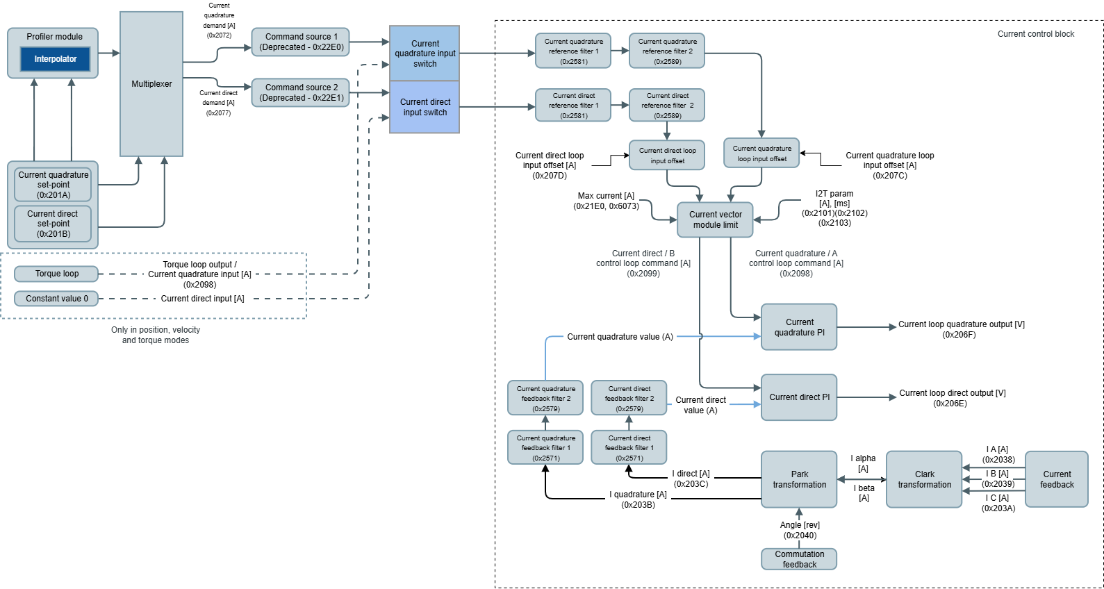
A current limit block is available to protect the system in front of high commanded currents or the excessive amount of energy accumulated (I2T). Max. current and I2T parameters determine this limit and are applied to both current quadrature demand and current direct demand. The output of the PI is directly connected to the voltage demands signals of the Voltage mode.
Warning
When the commutation modulation type parameter is set to Brushless DC or Brushed DC, only the current quadrature path is used. In this case, the Current direct actual value will be forced to 0, and the current direct input will have no effect.
The current feedback delivers current A value, current B value, and current C value. Internal FOC (Field Oriented Control) algorithm converts these inputs into the PI feedbacks current quadrature value and current direct value. How the current feedbacks is obtained is product-dependent.
The current feedback chain is described in the Feedbacks section.
All current modes work with two PI in parallel (quadrature and direct components). The implemented PI module follows the next block diagram:
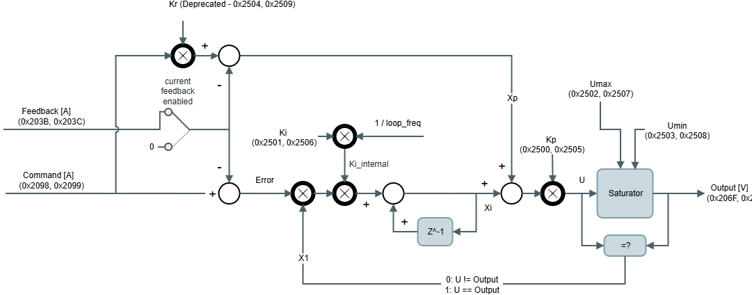
The output of the control loop at the kth sample is:
Where:
U is the output before entering in the saturator, in [V].
The output voltage value is also expressed in [V]. It is limited to the values Umax and Umin, so if the U signal is outside these parameters, the output is clamped.Command c is the Command signal (Output of the Reference + Filters + offset), in [A].
Feedback f is the Filtered Feedback signal (Output of the Feedback + Filters), in [A].
Kp & Ki are the PI gains. Kp in [V/A] and Ki in [Hz].
Ki_internal is non-dimensional.xp is the proportional path:
Kr is the set-point weight, used to choose between topologies PI, IP or mixed, it's non-dimensional (Deprecated).
xi is the integral path:
x1 is:
All current modes work with two PI in parallel and its related registers are:
0x2500 - Current quadrature loop Kp and 0x2505 - Current direct loop Kp (Kp).
0x2501 - Current quadrature loop Ki and 0x2506 - Current direct loop Ki (Ki).
0x2504 - DEPRECATED - Current quadrature loop Kr and 0x2509 - DEPRECATED - Current direct loop Kr (Kr).
0x2502 - Current quadrature loop max. out and 0x2507 - Current direct loop max. out (Umax).
0x2503 - Current quadrature loop min. out and 0x2508 - Current direct loop min. out (Umin).
0x2072 - Current quadrature demand anare the reference input of the PI.
Current direct set-point and current quadrature set-point are the targets commanded to the current modes of operation.
Current direct/B command and current quadrature/A command are the command values after the filter and offset is applied (Command signal from the diagram).
Current direct control loop error and current quadrature/A control loop error is the difference between the reference and feedback values in the control loop (Control loop error signal from the diagram).
Current direct value and current quadrature value are the feedback input after the filter is applied (Feedback signal from the diagram).
Voltage direct command and Voltage quadrature command are the output of the PI (Output signal from the diagram).
On the other hand, the implemented controller supports additional features:
Current feedback enabled allows opening the loop of the PI. It is configured with register control loop feedback options. The feedback path is removed from the real feedback signal and it forces a value of 0.
Current loop rate contains the update rate of execution of these PIs.
Current loop statusword contains information of PI functionality:
Loop enabled. This flag activates if the current loop is enabled and in use.
Upper saturator active (momentary). This flag activates when the current loop is saturating on the upper limit. The flag deactivates when the upper saturation is not happening anymore.
Lower saturator active (momentary). This flag activates when the current loop is saturating on the lower limit. The flag deactivates when the lower saturation is not happening anymore.
I2T limiting (momentary). This flag activates when the current loop command is being limited by the I2T algorithm. The flag deactivates when the command stops being limited by the I2T.
Derating limiting (momentary). This flag activates when the current loop command is being limited by the derating algorithm. The flag deactivates when the command stops being limited by the derating.
Upper saturator active (latching). This flag activates when the current loop is saturating on the upper limit and does not deactivate if the condition changes.
Lower saturator active (latching). This flag activates when the current loop is saturating on the lower limit and does not deactivate if the condition changes.
I2T limiting (latching). This flag activates when the current loop command is being limited by the I2T algorithm and does not deactivate if the condition changes.
Derating limiting (latching). This flag activates when the current loop command is being limited by the derating algorithm and does not deactivate if the condition changes.
Note
The latching flags of the control loops status get reset whenever the power stage transitions to "operation enabled" state or whenever a current loop PID parameter is changed.
Filters and offset
Additionally to the PI controllers, two biquad filters in cascade are available for both PI input sources: Reference and feedback. The purpose of these filters differs on every application, but basically they help to improve feedback readings or compensate undesired system dynamics. There are multiple configurations for every filter:
Low pass filter
High pass filter
Band pass filter
Peak filter
Notch filter
Low shelf filter
High shelf filter
The next parameters configure every filter type
Filter type | Frequency | Q-factor | Gain (dB) |
|---|---|---|---|
Low pass | X | X | - |
High pass | X | X | - |
Band pass | X | X | - |
Peak | X | X | X |
Notch | X | X | - |
Low shelf | X | - | X |
High shelf | X | - | X |
The related parameters for filter configuration are:
Current reference filter 1 type & current reference filter 2 type
Current reference filter 1 frequency & current reference filter 2 frequency
Current reference filter 1 Q-factor& current reference filter 2 Q-factor
Current reference filter 1 gain & current reference filter 2 gain
Current feedback filter 1 type & current feedback filter 2 type
Current feedback filter 1 frequency & current feedback filter 2 frequency
Current feedback filter 1 Q-factor& current feedback filter 2 Q-factor
Current feedback filter 1 gain & current feedback filter 2 gain
The configured filter is applied to both components quadrature and direct at the same time.
In some applications, the PI and the filters are not enough for proper control. In these cases, there is an additional input through the reference signal to the PI (after filters are applied) that is identified as Offset in the PID diagram. The purpose of these current quadrature loop input offset and current direct loop input offset is to be used by an external main device/instance to compensate for the system dynamics based on information that cannot be read directly by the drive.
Closing upper loops on the main device/instance
In some applications, the drive is configured to work in current mode with a "simple" controller diagram whereas the position and velocity loops are implemented by an external main device/instance. For those applications where additional feedback is required to be monitored outside the drive, an auxiliary feedback sensor is available to map extra feedback to the drive. The readings are available on auxiliary feedback value in raw format (cnt). Any mappable feedback used for position and velocity can be used as an auxiliary feedback sensor.
Current (C) mode description
Current (C) mode uses the above control scheme, connecting the current direct set-point and current quadrature set-point inputs from the application directly to the current direct demand and current quadrature demand signals mentioned above.
Note
Set-points will begin being taken into account after transitioning to the "operation enabled" state on the drive.
Cyclic Synchronous Current (CSC) mode description
Cyclic Synchronous Current mode (CSC) uses the above control scheme as well but connects current direct set-point and current quadrature set-point inputs to the interpolator from the set-point manager. The interpolator will begin to generate current direct demand and current quadrature demand after a change in any of the previous signals.
Warning
It is mandatory to configure the interpolation time mantissa and interpolation time exponent. The value of these parameters will determine how the interpolation will be performed. The product of these two parameters should match the time that will take to update the current quadrature set-point. More information about the interpolator can be found in the set-point manager.
Note
Interpolations will begin immediately upon a change of current quadrature set-point or current demand set-point
Warning
When the commutation modulation type parameter is set to Brushless DC or Brushed DC, only the current quadrature control is used. However, both of the current inputs (direct and quadrature) are still used for processing some protections (I2T, derating). In this case, make sure the current direct set-point and current direct loop input offset are set to 0
Current Amplifier (CA) mode
This mode is used to command the current of every phase driven through the actuator.
Control scheme
If software position limits are enabled using this mode of operation, the drive will generate a fault if the position limits are exceeded. Set them to 0 to disable this functionality
If actuator velocity overcomes the max. velocity parameter using this mode of operation, the drive will generate a fault. Disable the fault generation masking it.
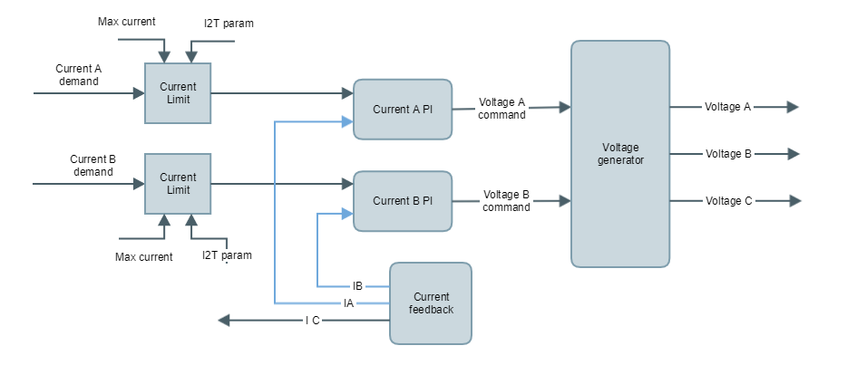
The current limit block is available to protect the system in front of high commanded currents or the excessive amount of energy accumulated (I2T). The output of the PI is directly connected to the voltage demands signals of the Voltage mode.
The implemented PI module follows exactly the same scheme as other current modes and the equations are the same. The difference is the involved signals:
Current A demand and current B demand are the reference input of the PI (Reference signal from the diagram).
Current direct/B command and current quadrature/A command are the command values after the filter and offset is applied (Command signal from the diagram).
Current A value, current B value are the feedback input after the filter is applied (Filtered Feedback signal from the diagram).
Current C value is indirectly used as feedback also (A, B and C current magnitudes are linked by Kirchhoff's law)
Voltage direct command and Voltage quadrature command are the output of the PI (Output signal from the diagram)
On the other hand, the implemented PI supports additional features that help during the tuning of the PI:
Current loop feedback bypass allows opening the loop of the PI. The feedback path is removed from the real feedback signals and it forces a value of 0.
Current loop rate contains the update rate of execution of these PIs.
Current loop statusword contains information of PI functionality:
Loop enabled. This flag activates if the current loop is enabled and in use.
Upper saturator active (momentary). This flag activates when the current loop is saturating on the upper limit. The flag deactivates when the upper saturation is not happening anymore.
Lower saturator active (momentary). This flag activates when the current loop is saturating on the lower limit. The flag deactivates when the lower saturation is not happening anymore.
I2T limiting (momentary). This flag activates when the current loop command is being limited by the I2T algorithm. The flag deactivates when the command stops being limited by the I2T.
Derating limiting (momentary). This flag activates when the current loop command is being limited by the derating algorithm. The flag deactivates when the command stops being limited by the derating.
Upper saturator active (latching). This flag activates when the current loop is saturating on the upper limit and does not deactivate if the condition changes.
Lower saturator active (latching). This flag activates when the current loop is saturating on the lower limit and does not deactivate if the condition changes.
I2T limiting (latching). This flag activates when the current loop command is being limited by the I2T algorithm and does not deactivate if the condition changes.
Derating limiting (latching). This flag activates when the current loop command is being limited by the derating algorithm and does not deactivate if the condition changes.
Note
The latching flags of the control loops status get reset whenever the power stage transitions to "operation enabled" state or whenever a current loop PID parameter is changed.
The input current values reference and feedback are expressed A. The output voltage value is expressed V.
The PI controllers used in this mode are exactly the same than the above ones.
Therefore the PI for phase A is configured with parameters:
Current quadrature loop Kp
Current quadrature loop Ki
Current quadrature loop Kr
Current quadrature loop max. out (Umax)
Current quadrature loop min. out (Umin)
And for phase B:
Current direct loop Kp
Current direct loop Ki
Current direct loop Kr
Current direct loop max. out (Umax)
Current direct loop min. out (Umin)