Updating DEN-NET-C (CANopen option)
Quick guide
In this article, we explain how to update the firmware through CAN of your CANopen Summit drive. Motionlab software is used.
After a firmware update, it is necessary to follow a special procedure before using the drive:
- Update the firmware.
- Once the firmware has been updated, restore the drive to defaults (restore all).
- Power-cycle the drive.
- Now the drive is ready again for operation.
firmware files
Everest series use .sfu firmware files. Nevertheless, Capitan, Denali and Everest S series use .lfu firmware files, and they are not compatible.
Loading firmware with the drive connected
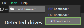
1. Navigate to "Tools" → "Load Firmware" the CAN Bootloader:
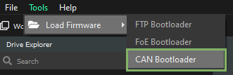
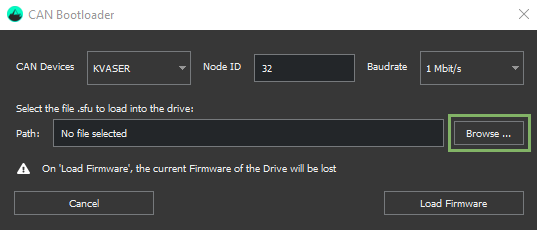
2. Click on "Browse" to choose the firmware file to be loaded (.sfu is for EVE and .lfu for the rest of the drives, including EVS). The file can be found in the Downloads section of the respective product.
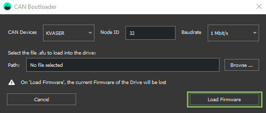
3. Click on "Load Firmware" to update the firmware.
4. Once the process finishes, a success message indicating the drive's firmware has been successfully updated is shown.
Loading firmware with the drive initially disconnected
1. Navigate to "Tools" → "Load Firmware" the CAN Bootloader:
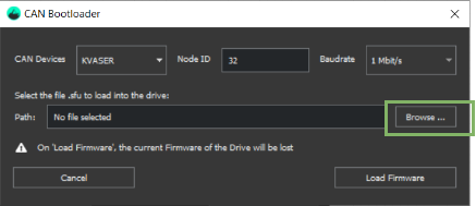
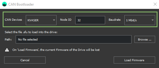
2. Select the proper proper CAN device, target the right node ID and Baudrate:
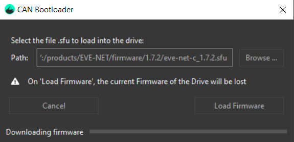
3. Click on "Browse" to choose the firmware file to be loaded (.sfu is for EVE and .lfu for the rest of the drives, including EVS). The file can be found in the Downloads section of the respective product.
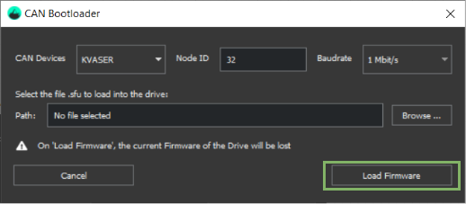
4. Click on "Load Firmware" to update the firmware.
5. After the process is finished we will see a success message indicating the drive's firmware has been successfully updated.
If the firmware update fails, re-try the process.
In case, recover of the drive is required, follow the procedure here: How to recover the drive after a failed firmware update .
CANopen bootloader reference
Firmware can be uploaded by CAN interface using CANopen standard registers defined in CiA302-3.
The bootloader procedure is only available while the drive is in NMT pre-operational state.
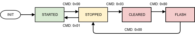
Program state machine
The program update procedure is based in an additional state machine that controls the program status. This state machine can be modified by means of register 0x1F51.
Index | Sub Index | Name | Data Type | Acc. | Pdo Map. | NVM | Value range | Default value | Units |
|---|---|---|---|---|---|---|---|---|---|
0x1F51 | 0x01 | Program control 1 | UINT8 | RW | No | No | UINT8 | 0x01 | - |
The values that this register can acquire corresponds to different states of the bootloader state machine.
0x00, Program stopped: There is a valid application in the flash, the application is not running.
0x01, Program started: There is a valid application in the flash, the application is running.
0x03, Program cleared (no program): There is no valid application in the flash.
0x80, Program flashing: The program is being flashed.
Alternatively, a write to Program control 1 register sends a command to the state machine manager.
0x00, Stop program: The application is stopped (transition available in started and flashing states).
0x01, Start program: The application is started (transition only available in stopped state).
0x03, Clear program: Clear the program (transition only available in stopped state).
0x80, Flash program: Enters in flashing mode (the program can be downloaded to the drive using register 0x1F50).
If a clear program command is sent to the drive while it is in Program stopped state, the program will be cleared. This action cannot be reverted!
Program download
Program can be downloaded while the drive is in Program flashing state using register 0x1F50.
Index | Sub Index | Name | Data Type | Acc. | Pdo Map. | NVM | Value range | Default value | Units |
|---|---|---|---|---|---|---|---|---|---|
0x1F50 | 0x01 | Program data 1 | DOMAIN | RW | No | No | - | 0x00 | - |
The content of the SFU/LFU file must be sent to this register by SDO messages. SDO block download is supported with a maximum block size of 256 Bytes.
Software identification
An additional register is available to check the software identification number of the loaded program.
Index | Sub Index | Name | Data Type | Acc. | Pdo Map. | NVM | Value range | Default value | Units |
|---|---|---|---|---|---|---|---|---|---|
0x1F56 | 0x01 | Program software identification 1 | UINT32 | RO | No | No | UINT32 | - | - |
During the firmware update, this register will show a 0 value. The register will be updated when the firmware is updated in the flashing status and after reaching program stopped state with the flash CRC value.
After the program has been successfully updated (program status is 'started'), this register will show the revision number of the active program.
Flash status
Register 0x1F57 allow to know the result of the program update procedure.
Index | Sub Index | Name | Data Type | Acc. | Pdo Map. | NVM | Value range | Default value | Units |
|---|---|---|---|---|---|---|---|---|---|
0x1F57 | 0x01 | Flash status identification | UINT32 | RO | No | No | UINT32 | 0 | - |
The bit value description for this register is shown in this table:
Bit | Value | Description |
|---|---|---|
0 | 0 | Status ok, program software identification is valid. |
1 | Status in progress, software identification is not valid. | |
1 to 7 | 0 | No error. Valid program is available. |
3 | Data format error or CRC error. | |
7 | Flash memory is protected (no write allowed). | |
*All other bits/values are reserved. | ||
Status in progress will be shown after reaching program cleared state. Although this, all other bits will show additional information about the state of the flash memory during all the process.
Clear program password
The clear program command is protected by a password. The password is "0x70636675" and can be introduced in register 0x5EDE, 0x00 - Boot mode.
Firmware update procedure
Enter in NMT pre-operational state.
Write "0x70636675" to the register 0x5EDE, 0x00. The drive will unlock the clear program command.
Send an SDO write message with command 0x00 to register 0x1F51, the drive will stop the application.
Send an SDO write message with command 0x03 to register 0x1F51, the drive clear the flash memory.
Send an SDO write message with command 0x80 to register 0x1F51, the drive will enter in flashing mode.
Send multiple SDO block download messages with the content of the SFU/LFU file to the register 0x1F50.
After the whole file has been written to the drive, send an SDO write message with command 0x00 to register 0x1F51, the drive will stop the download mode and check if the application is valid.
Send an SDO write message with command 0x01 to register 0x1F51, the drive will finish the bootloader process and start the new program.
LED signaling
After clearing the flash memory (the valid application), CANopen bootloader will start running. This is indicated by means of Red and Green LED (CANopen error and run LEDs), both LEDs will blink at 5Hz frequency.
When the flashing procedure is started, both leds will blink fast, at 10 Hz. LEDs signaling is shown in the following diagram:
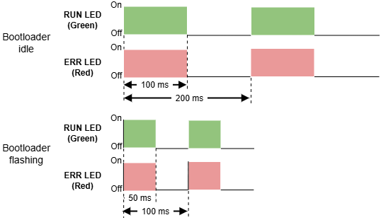
The normal LED sequence will be recovered when the new firmware is started.