Communications
The Denali XCR provides the following network communication interfaces.
Part number | Communication Option | P3 connector (ECAT 0) functionality | P4 connector (ECAT 1) functionality | P2 (I/O) connector pins 9, 11 |
|---|---|---|---|---|
DEN-XCR-C | Not used. | EtherNET standard port (default address 192.168.2.22). | CANopen interface CAN_H and CAN_L. | |
DEN-XCR-E | EtherCAT INPUT port 0. Motion Lab 3 can be accessed via Beckhoff Twincat tool from a PC. | EtherCAT OUTPUT port 1 | Not used. |
DEN-XCR-C (CANopen & Ethernet Interface)
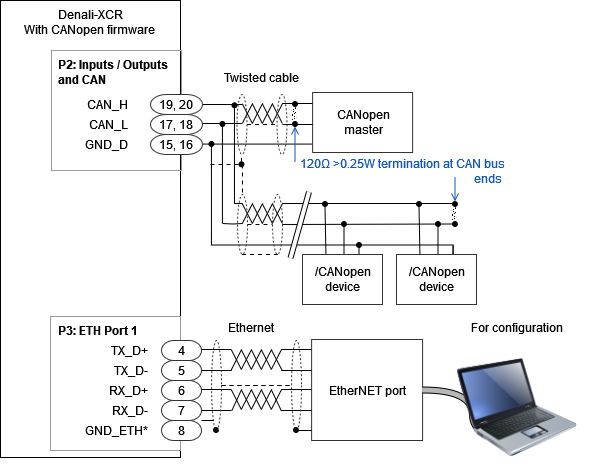
The Servo Drive supports the CANopen interface, a multi-terminal communication protocol based on CAN (Controller Area Network) bus. P3 connector ETH Port 1 (only) could be used with a standard Ethernet port for configuration. The drive CAN interface is not isolated. If your computer has no Ethernet port, you can use an Ethernet - USB adapter, like TeckNet HU043.
It is possible to control a servo drive from a CAN Master or from a computer with a CAN transceiver. Some USB to CAN transceivers that work with Everest XCR are indicated here: Kvaser Leaf SemiPro HS (EAN: 73-30130-00242-5), Kvaser Leaf Professional Rugged HS (EAN: 73-30130-00509-9), Peak Systems PCAN-USB (IPEH-002021), Peak Systems PCAN-USB opto-decoupled (IPEH-002022). Always ensure to have the drivers installed prior to connection.
An example of the required wiring for the CANopen interface is shown in the next figure.
CAN wiring recommendations
Build CAN network using cables with 2-pairs of twisted wires (2 wires/pair) as follows: one pair for CAN_H with CAN_L and the other pair for GND.
Do not make a 2 wire only interface. Not connecting the CAN GND may result in loss of data and poor EMC performance.
Cable impedance should have an impedance of 100 to 140 Ω (120 Ω typical) and a capacitance below 30 pF/meter.
Whenever possible, use bus links between the CAN nodes. Avoid using stubs (a "T" connection, where a derivation is taken from the main bus). If stubs cannot be avoided, keep them as short as possible. For maximum speed (1 Mbps), use a stub length lower than 0.3 meters.
For a total CAN bus length over 40 meters, it is mandatory to use shielded twisted cables. Connect the cable shield to GND at both ends. Ensure that the cable shield is connected to the connector shield, as the connection to host GND is usually soldered inside the connector.
Drive ID
When installing CANopen communication, ensure that each servo drive is allocated a unique ID. Otherwise, CANopen network may hang.
Lors de l'installation de la communication CANopen, assurez-vous que chaque servomoteur se voit attribuer un identifiant unique. Sinon, le réseau CANopen risque de se bloquer.
DEN-XCR-E (EtherCAT Interface)
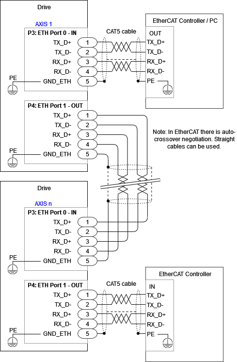
The Servo Drive provides access to the EtherCAT field bus system. EtherCAT is an isolated bus suitable for hard and soft real-time requirements in automation technology, test and measurement, and many other applications. The drive can be accessed and configured using any EtherCAT master over EtherCAT connecting the PC to the port 0 (in).
The next figure shows how to connect the drive in an EtherCAT bus. It is recommended to follow the standard IEC 61918-2013 for best practices.
Recommended EtherCAT cables and connectors
The following table shows the recommended connectors and cable colors for EtherCAT according to IEC 61918 Appendix H.
Signal | Function | Corresponding pin on drive | Suggested pinout M12-4 D-coded industrial Ethernet | Suggested pinout RJ45 LAN connector | Cable colour as per TIA-568B | Cable colour as per EN61918 |
|---|---|---|---|---|---|---|
- | Safety inputs / STO inputs | 1, 2, 3 | - | - | - | - |
TX_D+ | Transmit data + | 4 | 1 | 1 | White / Orange | Yellow |
TX_D- | Transmit data - | 5 | 3 | 2 | Orange | Orange |
RX_D+ | Receive data + | 6 | 2 | 3 | White / Green | White |
RX_D- | Receive data - | 7 | 4 | 6 | Green | Blue |
GND_ETH/PE | Connection for the EtherCAT cable shield. This pin is directly connected to the chassis of the drive - PE. It is recommended to use a cable shield termination with the same properties as TE S02-16-R. | 8 | Housing / Shield | Shroud / Shield | Metal | Metal |
Image of the connector | 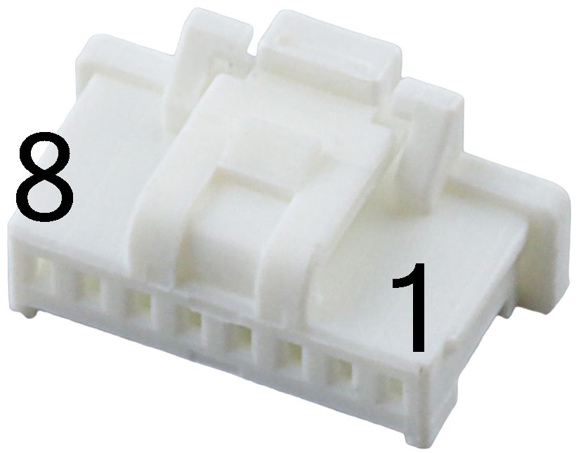 | 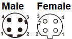 | 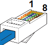 | |||