Inputs and Outputs
The Servo Drive provides several inputs and output terminals for parameter observation and drive control options.
1x General purpose 5V supply (+5V_I/O)
2x Digital Inputs (IN1, IN2).
2x Analog Inputs (AN1+, AN1-, AN2+, AN2-).
4x Digital Outputs (OUT1, OUT2, OUT3, OUT4).
1x Analog output (AN_OUT).
Non-isolated I/O
The inputs and outputs are not isolated. The reference voltage of the drive (GND_D) and the ground of the devices connected to I/Os must be the same. Otherwise, inputs or outputs may be damaged.
Reinforced isolation is necessary for electromagnetically noisy environments and for signals that could be user-accessible and cause electric shock. It is recommended to use isolators like Silicon Labs Si87xx series or Texas Instruments ISO121x.
General purpose 5V supply (+5V_I/O)
A 5 V 50 mA supply is available at pin 1 of the I/Os connector.
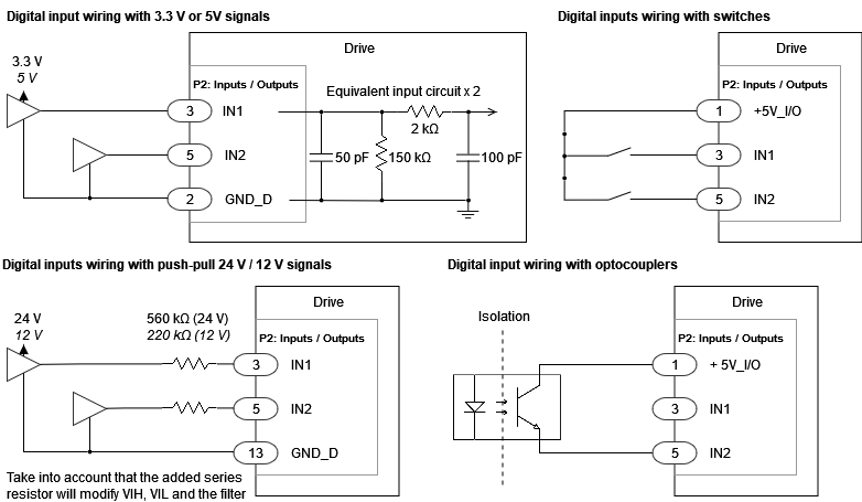
Digital Inputs Interface
The non-isolated digital inputs are ready for 3.3 V or 5 V digital levels. The following table shows their electrical specifications.
Specification | Value |
|---|---|
Number of inputs | 2 (IN1, IN2) |
Type of input | Single ended |
ESD capability | IEC 61000-4-2 (ESD) ± 15 kV (air), ± 8 kV (contact) |
Input current | 23 µA at 3.3 V input |
Maximum input voltage range | -0.5 V ~ +5.5 V |
High level input voltage | > 2 V |
Low level input voltage | < 0.8 V |
Minimum hysteresis | 150 mV |
1st order filter cutting frequency (-3 dB) | 800 kHz |
Next figure shows an example of how to wire digital inputs with various input options. For higher voltage systems like 12 V or 24 V a series resistance should be connected to the input.
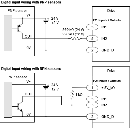
The interface for 3 wire NPN and PNP sensors is shown next.
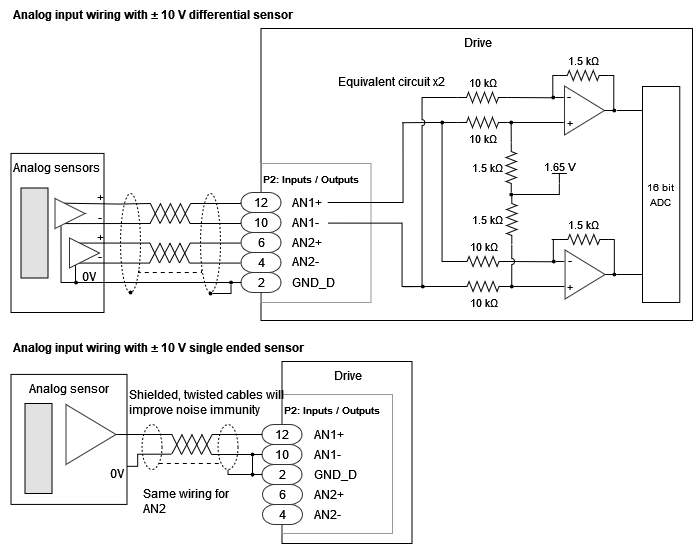
Analog Input Interface
The drive has a high accuracy fully differential 16-bit analog input AN1. See the specifications next:
Specification | Value |
|---|---|
Type of input | Differential |
ESD capability | IEC 61000-4-2 (ESD) ± 15 kV (air), ± 8 kV (contact) |
Input voltage range | ±10 V differential to avoid saturation (AN1+ - AN1-) |
Analog input resolution | 16 bits, 0.34425 mV/ADC count (Theoretical values: +10 V → 61817 ADC counts. 0 V → 32768. -10 V → 3719 ADC counts) |
Maximum absolute voltage on any pin (AN1+ or AN1-) | ±15 V |
1st order filter cutting frequency (-3 dB) | 10 kHz |
Next figure shows how to connect the analog input. Note that for single-ended inputs it is recommended to connect the negative AN1- to GND_D.
Also, for long distances, twisted pair, shielded cables are preferred. Connecting the shield to GND will improve the signal to noise ratio. However, take precautions not to connect the shield to PE as this could actually increase the noise of the signals.
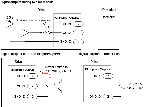
Digital Outputs Interface
The Servo Drive has 2 non-isolated digital outputs. These outputs can be used to drive optocouplers, LEDs or other digital circuits.
Specification | Value |
|---|---|
Number of outputs | 2 |
Type of output | Push-pull output at 3.3 V 400 Ω output impedance |
ESD capability | IEC 61000-4-2 (ESD) ± 15 kV (air), ± 8 kV (contact) |
Maximum sink/source current | ±10 mA. This depends on the specific application, please consider maximum acceptable voltage drop due to the output impedance (i.e. < 1 mA to ensure Vout > 2.7 mA) |
Unloaded output high voltage | 3.1 V ~ 3.4 V |
Unloaded output low voltage | 0 ~ 0.2 V |
The wiring of the digital outputs is shown next:
Analog Output Interface
The Servo Drive has 1 non-isolated analog output.
Specification | Value |
|---|---|
Number of outputs | 1 |
Type of output | ESD protected 1 mA maximum current (~55 Ω output impedance) |
ESD capability | IEC 61000-4-2 (ESD) ± 8 kV |
Voltage range | 0 V ~ 3.3 V |