EMCL Overview
Some of the main features of EMCL are:
- It allows to manage, transparent to the user, a wide range of motor technologies: PMSM (BLDC and BLAC), DC, voice coil, steppers and AC induction motors.
- It includes different motion modes (profiled position, profiled velocity, profiled torque, etc.).
- It includes different control modes (torque, velocity and position) with high update rates (10 kHz, 1 kHz and 1 kHz respectively).
- It grants high accuracy in torque control due to the use of vector control (field oriented control).
- It includes general purpose digital and analog inputs and outputs that can be used for further system control or signaling.
- It uses standard communications protocols for extended compatibility. It is CANopen CiA-301, CiA-305 and CiA-402 compliant, as well as including a RS-232 proprietary protocol also based on CANopen.
- A programming language to store routines in its NVM has been defined, allowing the motion controller to work in stand-alone mode.
EMCL features
| Controllable motors |
Both rotary and linear motors can be controlled. | |
| Torque feedback sensor |
| |
| Velocity feedback sensor |
| |
| Position feedback allowed |
| |
| Digital inputs | Up to 8. | |
| Digital outputs | Up to 8. | |
| Analog input | Up to 3. Programmable. | |
| Analog outputs | Up to 2. Programmable. | |
| Command sources |
| |
| ||
| ||
| Analog input options:
Updated at 10 kHz (CST) Updated at 1 kHz (all other modes) | |
|
| |
|
| |
|
| |
| Shunt regulator | ||
| Brake |
| |
| Flexible signaling monitor |
| |
| Motion modes |
| |
| Control modes |
| |
| Electronical Commutation for brushless motors |
| |
| Communications |
| |
| Motion controller capabilities | It has an internal programmable language that allows working completely in stand-alone mode. | |
| Protections |
|
EMCL structure
The EMCL structure is based on an object dictionary. Each object is simply a memory address in which a value is stored, the meaning of which will depend on the object. Examples of objects are the current position, or the target speed, or the current running through the motor. Internal EMCL processes use objects to carry out functions and to deposit the results of operations, and these objects may be read and/or written using the featured communication protocols.
Some objects may be saved in the non-volatile memory of the system, enabling its value to be available after power-off. This feature allows to avoid object reconfiguration after every power on. In addition, the NVM saving and recovery process is also accessible through objects.
The following figure shows a summarized diagram of EMCL architecture for internal handling of objects:
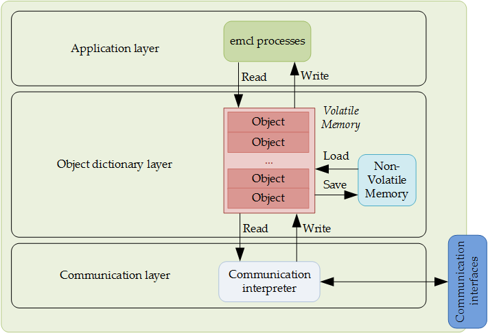
As it can be observed, EMCL internal architecture can be divided in three layers:
- Communication: This layer provides the communication objects and the appropriate functionality to transport data via communication ports.
- Object dictionary: The object dictionary is a collection of all the data items which have an influence on the behavior of the application objects, communication objects and state machine of the controller.
- Application: The application comprises the functionality of the device with respect to the interaction with the process environment.
Object structure
Each object or register contain the following information:
Index / SubIndex | Specifies the object number. |
|---|---|
Name | Specifies the object name. |
Object type | Specifies the object type. |
Access | Specifies the type of object access. |
Data type | Specifies the data type. |
PDO mapping | Specifies if object could be accessed via PDO (only valid for CANopen communications). |
Value range | Specifies the range of allowed values. |
Default value | Specifies the default value of the object. |
A 16-bit Index is used to address all objects within the object dictionary. In case of a simple variable Index references the value of this variable directly. In case of records and arrays however, Index addresses the whole data structure. To allow individual element of structures of data to be accessed a 8-bit SubIndex is defined.
Possible object types are:
- VAR: It indicates that is using a basic type value (UINT8, INT16, STR, etc).
- ARRAY: It indicates that is a data set of the same basic type, i.e. UINT16. In that case, SubIndex zero is always an UINT8 that indicates the length of the array. Hence, the zero SubIndex in arrays can not be used.
- RECORD: It indicates that is a data set with different basic types. In that case, SubIndex zero is always an UINT8 that indicates the number of items in the record. Hence, the zero SubIndex in arrays can not be used.
Possible access types are:
- Read/Write (RW): Read and write access. The object can be consulted and modified.
- Read only (RO): Read-only access. The object can only be consulted.
- Constant (CONST): The object is constant and can only be consulted.
- Write only (WO): Write-only access. The object can only be modified.
Possible data types are:
- UINT8: 1 byte size. Value range [0 to 255]
- UINT16: 2 byte size. Value range [0 to 65535]
- UINT32: 4 byte size. Value range [0 to 4294967295]
- UINT64: 8 byte size. Value range [0 to 18446744073709551616]
- INT8: 1 byte size. Value range [-128 to 127]
- INT16: 2 byte size. Range of values: [-32768 to 32767]
- INT32: 4 byte size. Range of values: [-2147483648 to 2147483647]
- STR: Character sequence terminated with a null character. Variable size between 1 and 8 bytes. The equivalent binary display is sent in RS-232 communications.
Elements stored in non-volatile memory are reloaded with the last value saved when starting the system. The list of objects saved into NVM can be found in the description of the object, as well as in appendices A, B and C. Other parameters are reset at the default value.