SSI absolute encoder
Synchronous Serial Interface (SSI) is a widely used serial interface standard for industrial applications between a controller and a sensor. SSI is based on RS-422 standards and has a high protocol efficiency in addition to its implementation over various hardware platforms, making it very popular among sensor manufacturers
EMCL supports a wide range of protocols over the SSI interface to communicate with absolute position encoders.
SSI frame configuration
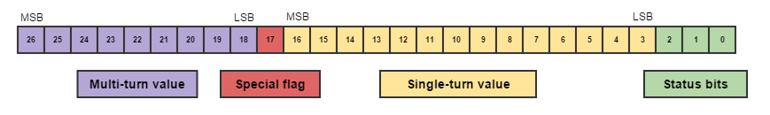
There are a lot of different SSI frames in the sensor world. Each manufacturer has its own frame and it's difficult to find a common standard. The EMCL overcomes this factor using a generic decoding algorithm that allows to interface most of the SSI encoders in the market. This algorithm expects that all SSI frames always contain bits dedicated to the position value. These bits may be encapsulated in a single set of bits or may be divided into single-turn and multi-turn bits. Therefore, all the information that this algorithm needs to decode the position value of a SSI encoder is:
- 0x2380; 0x04 - Max. clock rate. Indicates the maximum clock rate of the SSI encoder.
- 0x2380; 0x02 - Frame size. Indicates the total frame size, including position bits and special bits (like error flags).
- 0x2380; 0x03 - Codification. Indicates the codification of the position value bits (typically gray or binary codification).
- 0x2380; 0x05 - Single-turn bits. Indicates the number of bits used in the bitfield used to represent the single-turn value.
- 0x2380; 0x06 - Single-turn start bit. Indicates the position in the SSI frame of the first single-turn bit.
- 0x2380; 0x07 - Multi-turn bits. Indicates the number of bits in the bitfield used to represent the multi-turn value.
- 0x2380; 0x08 - Multi-turn start bit. Indicates the position in the SSI frame of the first multi-turn bit.
With this parameters, the EMCL is able to get the total position value from the SSI encoder.
Note
The bits remaining to cover a 32-bit position will be calculated by the device with versions later to 2.7.6
This algorithm only reads position values. It is not able to detect error flags or special features coded into the SSI frame. For that purpose, read the next section.
Example
The next SSI frame is generated by a encoder in binary codification:
The configuration needed to decode the total position value is:
- Frame size. 27
- Codification. 0 (binary)
- Single-turn bits. 14
- Single-turn start bit. 3
- Multi-turn bits. 9
- Multi-turn start bit . 18
SSI frame types
The generic algorithm is not able to process the special bits of a SSI frame. For this purpose, the EMCL defines different SSI frame types which locates the special bits position into the frame. These bits are processed independently from the generic algorithm, which means that the generic algorithm has to be always properly configured for a correct operation.
The EMCL reaction in front of the "activation" of a special bit depends on each frame type.
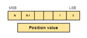
Type 0
This type of frame doesn't have special bits by definition. If the manufacturer specifies a number of special bits that differs from type 1 and type 2 formats, the fields of interest in the frame (i.e. Multiturn bits/ single-turn bits) should be specified in the configuration register 0x2380. This way, only the bits containing single-turn and multiturn information will be read.
Type 1
This frame contains three special bits at the end of the frame
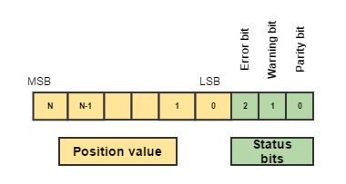
- Error bit. If active ('1'), the read frame is ignored.
- Warning bit. Not used.
- Parity bit. If it does not match with the expected, the read frame is ignored.
Type 2
This frame contains 1 error bit at the end of the frame.
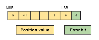
- Error bit. If active ('1'), the read frame is ignored.
Single-Turn encoders
Note
This information is only valid on versions prior to 2.7.6
In case the SSI encoder only has single-turn data, the EMCL computes the multi-turn part by software. This avoids undesired behaviours during position mode operations. The variable size of the computed multi-turn part is:
Therefore, the maximum position range reached in this mode is a UINT32.
SSI encoder as commutation feedback
SSI encoder is able to measure the rotor electrical angle because it contains the information of 1 mechanical revolution in the single-turn part of the frame. As it is itself an absolute encoder, only an initial calibration is required the first time the system is configured.
SSI absolute encoder measurements are slower than incremental options like SinCos or digital encoder, so if they are used for commutation, the efficiency of the system could decrease respect using an incremental option.
It is recommended to install SSI only firmware variant if SSI absolute encoder is used as commutation feedback.
- EMCL Standard variant: update rate is 1KHz.
- EMCL SSI only variant: update rate up to 10KHz.
Recommendations for using SSI absolute encoder as commutation feedback with SSI only firmware variant:
- Ensure that the used SSI encoder supports at least 10KHz update rate. It is possible to reduce the update rate of the feedback, but it will negatively affect to the efficiency of the system.
- Use the highest baudrate supported by the feedback, ensuring that the frame length does not overlap between two consecutive read periods.
- Use binary encoder instead of Gray encoder.
SSI encoder as reference feedback
Absolute encoders are the best option to use as reference feedback. Only an initial calibration is required the first time the system is configured. Then, any incremental encoder is able to be used as commutation feedback, taking the initial rotor position information from the SSI encoder. So, initial phasing process are not required every time the system is powered up.
Related registers
0x2380 - SSI Absolute encoder configuration