COM-KIT Connectors and Pinout
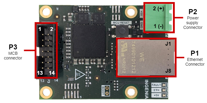
P1- Ethernet Connector
Connector
| PCB connector | Mating connector |
|---|---|
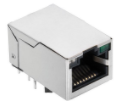 Wurth 74990101212 | 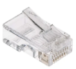 Standard RJ45 connector |
Pinout
| Pin | Signal | Description | Type |
|---|---|---|---|
| J1 | TX+ | Transmit + line | Signal |
| J2 | TX- | Transmit - line | Signal |
| J3 | RX+ | Receive + line | Signal |
| J6 | RX- | Receive - line | Signal |
| J4, J5 | NC | J4 and J5 are internally shorted and terminated with 75 Ω. | - |
| J7, J8 | NC | J4 and J5 are internally shorted and terminated with 75 Ω. | - |
| CHASSIS | CHASSIS | The chassis is where the cable shield should be connected. It is decoupled to GND of the board with 1 nF 2 kV capacitor and a 1 MΩ discharge resistor. | Shield |
| Notes | |||
| Standard Ethernet and pinout. | |||
P2 - Logic Supply
Connector
| PCB connector | Mating connector |
|---|---|
 Phoenix Contact 1757242 |  Phoenix Contact 1757019 Included in the COM-KIT |
Pinout
| Pin | Signal name | Description | Type |
|---|---|---|---|
| 1 | GND_D | Digital Ground. This ground is the same as in the MCB interface and the drive. | Power |
| 2 | +5V_D | 5 V ± 10%, 500 mA maximum continuous logic supply input. Reverse polarity protected. | Power |
| Notes | |||
Since the digital ground of the COM-KIT and the drive and MCB is shared with the power supply ground, it is essential that the power supply is isolated. Good quality, isolated, USB chargers are a good option for power supply, use a flying lead cable like Qualtek 3021005-03 and connect red and black terminals to the Phoneix connector. It is also acceptable if the power supply comes from the interface board if sufficient power is available. This small ground loop is not problematic if cables are short. | |||
P3 - MCB interface
Connector
| PCB connector | Mating connector |
|---|---|
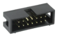 3M 30314-6002HB | 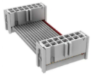 76 mm length 14 pin IDC connector 3M D89114-0131HK-3365/14-D-3 included in the COM-KIT. There are multiple alternative options. See Recommended MCB Cables. Note, MCB SPI signals operate at 50 MHz and are single-ended, take care to minimize cable length below 10 cm, and ensure GND returns are well wired. The commissioning kit must be placed close to the drive, and the signals should be kept away from noise sources such as motor phases. |
Pinout
For more detailed functionality, please check MCB pinout in the reference manual for further clarification on each signal.
| Pin | Signal name | Description | Type* | Pin | Signal name | Signal Description | Type* |
|---|---|---|---|---|---|---|---|
| 1 | FAULT_OUT | Fault signal output from the drive. When the drive has any fault it sets this signal HIGH. It is directly connected to the RED "Fault" LED on the commissioning kit. | Input | 2 | MCB_ENABLE | MCB enable pin. This pin is intended to change the multiplexer state in the interface board from master to commissioning kit board. It is tied internally to GND_D through a 1 kΩ pulldown on the commissioning kit. A 10 kΩ ~ 100 kΩ pull-up resistor must be added on the interface board, to ensure the signal is high when the commissioning kit is not physically connected. When MCB_EN = LOW (default state with commissioning kit connected) the master is disconnected (or reset), the commissioning kit can interface with the drive. When MCB_EN = HIGH. Default state when the commissioning kit is disconnected and The master is connected to the drive directly, | Output |
| 3 | \EXT_FAULT | External Fault signal. When low it creates a fault to the drive slave which disables the power. 0x2618 - External fault option code | Output | 4 | \HW_RESET | When low, it resets the motion control DSP of the drive. | Output |
| 5 | \MCB_SPI_CS | Chip Select signal for the SPI bus. When low, the data is transferred. | Output | 6 | MCB_SYNC0 | Synchronization signal between the internal control loops of the drive to a time reference set by the master. | Output |
| 7 | MCB_IRQ | Indicates when the device is ready to execute a new SPI transfer. | Input | 8 | MCB_SYNC1/BOOT | The drive generates a continuous pulse with the base time of the internal control loops. During boot-up, it is used to choose between entering in boot or application mode. | Input |
| 9 | MCB_SPI_MOSI | Master Output Slave Input signal of the SPI bus. | Output | 10 | GND_D | Digital Ground. | Power |
| 11 | MCB_SPI_MISO | Master Input Slave Output signal of the SPI bus | Input | 12 | MCB_SPI_CLK | The clock signal of the SPI bus is generated by the Commissioning Kit. | Output |
| 13 | GND_D | Digital Ground. | Power | 14 | VDD_MCB | Power supply detection input used for monitoring purposes (currently not implemented). | Input |
* The types are always from the Commissioning Kit point of view. The Commissioning Kit acts master from the MCB and the drive as a slave.