Frame
The transmitted frame through SPI is composed of the following fields:
|
Header (1 word) |
Config data |
Cyclic data (optional) |
CRC |
||
|---|---|---|---|---|---|
|
Address |
Command |
Pending frame |
|
|
|
|
12 bits |
3 bits |
1 bit |
4 word |
0 - 32 word |
1 word |
-
Header. It includes the master and slave commands.
-
Config data. Contains data from configuration access. If data is higher than 4 words, fragmentation is applied (see below).
-
Cyclic data. Contains data from cyclic access. This field is by default disabled.
-
CRC. CRC-CCITT (XModem) polynomial is used.
CRC parameter
Value
Width
16 bits
Polynomial
0x1021
Initial value (seed)
0x0000
Configuration access
Configuration access is the name used to identify acyclic/asynchronous requests from master to slave. This access type doesn't use the cyclic data field.
In configuration state, only configuration frames are allowed:
|
Config frame (only in config state) |
||
|---|---|---|
|
Header |
Config data |
CRC |
|
1 word |
4 word |
1 word |
In cyclic state, configuration access (acyclic) is also present, see below in cyclic frames.
Register addressing
The address field from the header is used to indicate the register to be accessed of the servo drive dictionary.
The maximum supported registers are 2048 (11 bits) so the first bit of the field (bit number 12) is reserved for future use and must be kept to 0.
|
Min register address |
Max register address |
|---|---|
|
0 |
2047 (0x7FF) |
Commands
The protocol is based on master-slave communication and all the commands sent by a master are confirmed by the slave, indicating the result of the operation. SPI interface transmits the master and slave messages at the same instant and clock rate. Therefore, idle ("dummy") frames are required by master and slave, so every configuration request is composed of 2 frames: request from master to slave, and reply from slave to master.
Next diagram shows how a configuration access is executed:
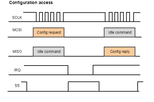
The IRQ signal indicates the status of the slave device:
-
A high level means that the slave is ready for receiving a new message from the master.
-
A low level means that the slave is processing data and its output buffer is empty, so if the master tries to send a config request, the slave reply will contain unkown data.
So the master must wait until slave IRQ becomes high before initiating any transmission.
A configuration request is divided into different commands that are classified as master or slave commands:
Master commands
-
Read Access 0b001. It is used to get a value from a drive register. Slave must reply with an ACK or Error on read (see below).
Read access to register 0x10
Header
Config data
CRC
Address
Command
Pending frame
0x010
0b001
0
0
0xA922
0x01020000000000000000A922
-
Write Access 0b010. It is used to set a value of a drive register. Slave must reply with an ACK or Error on write (see below).
Write access to register 0x10
Header
Config data
CRC
Address
Command
Pending frame
0x010
0b010
0
0x0006000000000000
0x528F
0x01040006000000000000528F
-
Get info command 0b000. It is used to obtain all the information of a register available on the MCB slave. Slave will reply with an ACK or Error . Data field from slave is coded in the next way:
LSB (bits)
0..7
8..13
14..15
16..18
18..63
MSB (bits)
Size
Data type
Cyclic type
Access type
Reserved
Number of bytes
INT16 → 0
Config → 0
READ → 3
UINT16 → 1
INT32 → 2
Cyclic Tx (drive to master) → 1
WRITE → 5
UINT32 → 3
FLOAT → 4
Cyclic Rx (master to drive) → 2
READ/WRITE → 7
STRING → 5
Getting information of register 0x011
Master request
Header
Config data
CRC
Address
Command
Pending frame
0x011
0b000
0
0x0000000000000000
0x7FB5
0x011000000000000000007FB5
Slave reply
Header
Config data
CRC
Address
Command
Pending frame
0x011
0b011
0
0x4102000300000000
0x28C1
0x0116410200030000000028C1
-
Idle command 0b111. It is used every time the master needs to send a frame without any configuration access.
Slave commands
-
ACK access 0b011. Indicates that the request has been processed correctly.
Successful reply to read access on register 0x10
Header
Config data
CRC
Address
Command
Pending frame
0x010
0b011
0
0x0006000000000000
0x94E8
0x0106000600000000000094E8
-
Error on read 0b101. Indicates that the read request has not been executed correctly. Config data includes an error code to indicate the reason.
Error reply to read access on register 0x10
Header
Config data
CRC
Address
Command
Pending frame
0x010
0b101
0
0x0607001000000000
0x304C
0x01090607001000000000304C
-
Error on write 0b110. Indicates that the read request has not been executed correctly. Config data includes an error code to indicate the reason.
Error reply to write access on register 0x10
Header
Config data
CRC
Address
Command
Pending frame
0x010
0b110
0
0x0607001000000000
0x4780
0x010C06070010000000004780
-
Idle command 0b111. It is used to indicate that slave reply is still being processed. It is used if configuration access is done when cyclic mode is enabled.
Error access codes
The possible error codes when a wrong access is detected are:
|
Error brief |
Error code |
Example description |
|---|---|---|
|
Unsupported access |
0x06010000 |
Try to write a read only register |
|
Register doesn't exist |
0x06020000 |
Register address doesn't exist into dictionary |
|
Incorrect mapping |
0x06040041 |
Register is not cyclic mappable |
|
Too much mapped registers |
0x06040042 |
Mapped registers don't fit into Cyclic frame |
|
General error |
0x08000000 |
Undefined error has been detected |
|
Invalid cyclic index |
0x08010000 |
A gap has been detected in the mapped register list |
|
Cyclic state is not reachable |
0x08010010 |
Cyclic state is not reachable for an unkown reason |
|
Configuration is not allowed |
0x08010020 |
Something in the mapping is wrong and cyclic mode is not reachable |
|
Invalid command |
0x08010030 |
Unknown command for the slave |
|
CRC error |
0x08010040 |
A CRC error has been detected |
Data field
Data field contains the data from a read or write request. It is sent word by word (independent of the used physical layer) and in LSW (least significant word first). Whenever it is possible, the words are sent in MSB (Most significant bit first).
Data 1311768467463790320 (0x123456789ABCDEF0) is sent in this order through data field:
0xDEF0 9ABC 5678 1234
Fragmentation
If the data field is higher than 4 words (for example for ID registers that contain strings) the message might be fragmented.
A configuration frame is divided into the needed number of configuration frames. All the frames, except the last one, set the pending frame bit indicating to the remote device that there are more frames to be read.
The string 0.1.2.3.4.5.6.7 (0x 30 2E 31 2E 32 2E 33 2E 34 2E 35 2E 36 2E 37) is sent by the slave using two frames:
Frame 1
|
Header |
Config data |
CRC |
||
|---|---|---|---|---|
|
Address |
Command |
Pending frame |
|
|
|
0x650 |
0b011 |
1 |
0x302E312E322E332E |
0x4672 |
|
0x6507302E312E322E332E4672 |
||||
Frame 2
|
Header |
Config data |
CRC |
||
|---|---|---|---|---|
|
Address |
Command |
Pending frame |
|
|
|
0x650 |
0b011 |
0 |
0x342E352E362E3700 |
0x6704 |
|
0x6506342E352E362E37006704 |
||||
Cyclic access
Cyclic access is the name used to identify cyclic/synchronous data exchange between master and slave. This access type uses the whole MCB frame and is only possible in the cyclic state. Even in cyclic state, the size of the frame remains fixed.
|
Cyclic frame |
|||
|---|---|---|---|
|
Header |
Config data |
Cyclic data |
CRC |
|
1 word |
4 Word |
0 - 32 word |
1 word |
Register addressing
In order to obtain the maximum efficiency of the transmission, the addressing of the cyclic data is done "offline".
See Enabling cyclic access and Mapping procedure sections (below) for further description about how to identify the content of the cyclic data and how to enable cyclic state.
On the other hand, the addressing of the config data is the same as described in the Configuration access section (above).
Commands
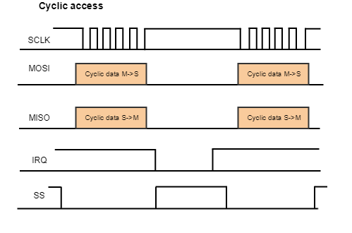
Cyclic data is not attached to any command. On every SPI transmission there is data from slave and master transferred at the same time:
Configuration data is attached to the same commands described in Configuration access section (above). However, when cyclic data is enabled, the sequence request-reply follows a different flow than the described above:
-
Header and config data field works exactly as in configuration access.
-
Cyclic data is exchanged cyclically to allow an external master to implement high-level control loops or complex profiles. Therefore cyclic access is faster than configuration access.
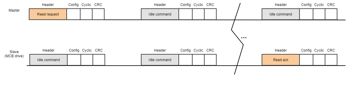
Then if the master sends a configuration request when cyclic mode is active, the slave reply might contain an empty configuration frame because it needs more time to process it.
Next diagram shows the workflow in case the configuration request cannot be replied in the next cyclic frame:
-
If there isn't a configuration frame to be sent, the master must send idle commands to indicate to the slave that there is nothing to process.
Why config frame is still sent in cyclic mode?
Config access is needed to enable and disable the cyclic mode (change MCB state). Furthermore, other configuration registers might be modified during cyclic operation.
Enabling cyclic state
Cyclic state is enabled by a special procedure. It consists of sending a command to a reserved dictionary register named communication state register. Then the drive performs several checkings looking at the mapped registers and finally modifies the expected frame size.
The communication state register is located at the address 0x640 and it accepts two possible values:
|
Register 0x640 (Communication state) |
|
|
Value |
Meaning |
|
1 |
Config access |
|
2 |
Cyclic access |
What does it mean mapped registers?
The key point of the cyclic access is that the drive doesn't need to process the header of the frame. A previous configuration of the cyclic data is done during the cyclic mode activation. A set of reserved dictionary registers are used to indicate to the network which register values are expected to be into the cyclic data field. This procedure is named mapping procedure (explained below).
Register 0x010 - Control word is going to be accessed:
Config mode
Master will send the command 0x01040006000000000000528F (see Master commands examples) . The slave will need to check the header, identify the address and the command, then look for the address into its internal dictionary, access to the internal variable and finally reply to the master request.
Cyclic mode
Network is already configured and register 0x010 is mapped into the cyclic data. Then the master sends the next command 0x000E0000000000000000000633BC. This frame has a void config frame. The slave just needs to take the word from the cyclic data 0x0006 and copy it into the internal variable because it already knows that belongs to the register 0x010.
Mapping procedure (enable cyclic state)
The exact steps are:
-
Disable cyclic access if enabled.
Set register 0x640 (communication state) to 1 to disable cyclic access.
-
Write the desired cyclic mapping registers.
Rx mapping registers (from master to slave) start at address 0x651 to 0x65F.
Tx mapping registers (from slave to master) start at address 0x661 to 0x66F.
The value to be written should be 32 bits and should have the following structure:MSWord
LSWord
Register size (in bytes)
Register address
When writing those registers the drive will check if the register address exists and if the size matches with the provided one. If not, an error will be returned and the object will not be mapped.
We want the following mapping:
-
Rx direction:
-
1st register: Register 0x038 that occupies 2 words (4 bytes).
-
2nd register: Register 0x456 that occupies 1 word.
-
-
Tx direction:
-
1st register: Register 0x205 that occupies 2 words.
-
The mapping should be as follows:
-
0x651 = 0x00040038.
-
0x652 = 0x00020456.
-
0x661 = 0x00040205.
-
-
Write number of entries of mapped registers to let the drive know how many registers should be processed.
Rx mapped registers: 0x650.
Tx mapped registers: 0x660.Following the above example, number of mapped registers will be:
-
0x650 = 2.
-
0x660 = 1.
When mapping the drive will check if the register address exists and if the size matches with the provided one. If not, an error will be returned and the object will not be mapped.
-
-
Enable cyclic access by setting register 0x640 to 2.
A validation of the current mapping configuration will be performed. If it is considered valid, the communications will allow cyclic access messages. Otherwise an error will be returned and the drive will remain in configuration access mode.
The drive will reply the 0x640 write request using the config access frame. Once is replied, size of the frame will change to the cyclic one. This is critical in interfaces such as SPI where the reply is sent using a idle frame from the master.
Master must wait for the drive reply before changing to cyclic access mode to verify that the new mode has been reached correctly.
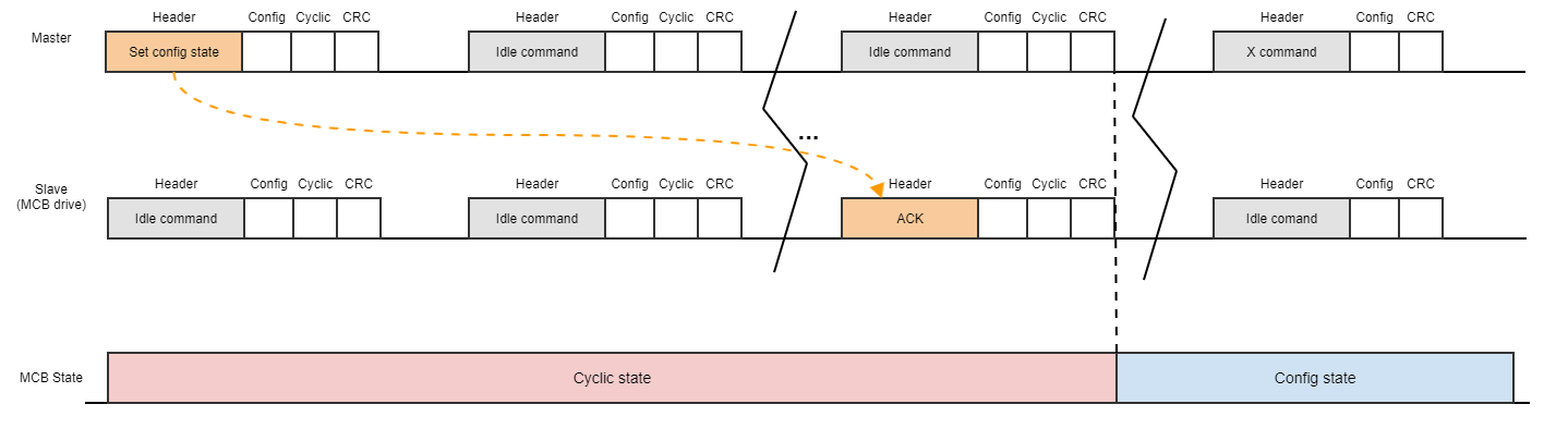
Disabling cyclic state (returning to config state)
-
Disable cyclic access.
Set register 0x640 (communication state) to 1 to disable cyclic access.
This command will be sent as a configuration access. -
Continue sending cyclic frames until the configuration response (an ACK) of the register 0x640 is received.
-
Just after receiving the ACK for the state change, the slave will be in config state, so no more cyclic frames can be sent from now on.
-
As now we are in config state, send config frames.
These steps can be shown in the next diagram: