Feedbacks
The Everest XCR can be connected to a maximum of 3 feedback devices at the same time that might be used for commutation and/or velocity/position control purposes. These devices are connected in the J1 connector of the board in with the following pin definitions:
| Feedback port | J1 connector pins | Allowed feedbacks |
|---|---|---|
| Digital Halls | 9 to 13 | Digital Halls, open collector or push-pull. |
| Absolute encoder 1 | 14 to 19 | SSI absolute encoder, Single BISS-C, Dual BiSS-C in daisy chain topology (up to 2) |
| Incremental encoder / Absolute encoder 2 | 1 to 8 | Quadrature incremental encoder (S0S90), SSI absolute encoder. |
Powering the feedbacks
A 5 V 200 mA overcurrent-protected output is provided to power external circuits, including feedback sensors.
If it is not used, and the sensor is powered externally, always remember to connect the ground or reference voltage to the Everest XCR.
Une sortie protégée contre les surintensités de 5 V 200 mA est fournie pour alimenter les circuits externes, y compris les capteurs de retour.
Si elle n'est pas utilisée et que le capteur est alimenté en externe, n'oubliez pas de connecter la terre ou la tension de référence à l'Everest XCR.
Digital Halls
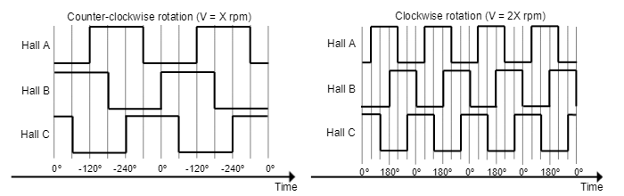
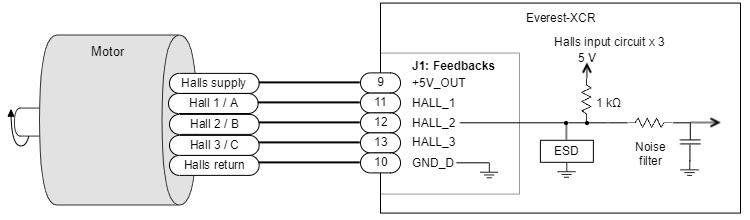
The Hall sensors are Hall effect devices that are built into the motor to detect the position of the rotor magnetic field. Usually, motors include 3 Hall sensors, spaced 120º (electrical degrees) apart that are in phase with the stator position. Using these 3 signals, the drive is capable to detect the position, direction, and velocity of the rotor. The Halls effect sensors are a good way to detect the phasing of the motor and avoid "wake and shake" movements. Everest XCR can use digital Hall sensors alone to drive the motor with trapezoidal commutation, but not with sinusoidal commutation due to the improper total resolution that the hall effect sensors have in comparison with other devices such as an incremental encoder.
This interface accepts 0 ~ 5 V level signals. Inputs are pulled up to 5 V with 1 kΩ, so industry-standard open collector and push-pull output Hall effect sensors can be connected. Next table summarizes digital Halls inputs main features:
Specification | Value |
|---|---|
Type of inputs | Single ended with pull-up and low pass filter |
Number of inputs | 3 |
ESD capability | IEC 61000-4-2 (ESD) ± 30 kV (air), ± 30 kV (contact) IEC 61000-4-5; tp = 8/20 μs 12 A, 200 W |
| Maximum voltage range | -0.5 ~ 5.5 V |
| Maximum recommended working frequency | 5 kHz |
1st order filter cutting frequency (-3dB) | 16 kHz |
| Sampling frequency | 10 ksps |
Type of sensors | Open collector |
| Pull-up resistor value | 1 kΩ |
Next figures show the typical waveforms of the digital Halls signals.
Next figure illustrates how to connect the digital Halls to Everest XCR and a simplified input schematic.
Velocity control with Halls
Due to the inherent low resolution of motor mounted Hall sensors, they are not recommended for velocity feedback in low speed applications.
Absolute Encoder 1
The Everest XCR servo drive absolute encoder 1 can be used as position, velocity, and commutation feedback device. This sensor generates digital data that represent the encoder actual position. From the position information, speed and direction of motion is calculated. The position is not lost even if the encoder is powered down, which means that it is not necessary to move to a reference position as with incremental type encoders. The following table shows the absolute encoder inputs electrical specifications.
Specification | Value |
|---|---|
Type of inputs | Differential / Single ended |
ESD capability | IEC 61000-4-2 (ESD) ± 30 kV (air), ± 30 kV (contact) IEC 61000-4-5; tp = 8/20 μs 12 A, 200 W |
| Maximum operating voltage range | -0.5 ~ 5.5 V |
| Operating frequency | 1 MHz to 10 MHz (user configurable) |
| Receiver hysteresis | min 50 mV typ 80 mV (DATA+ - DATA-) |
| Termination | 220 Ω differential on data line |
| Fail safe bias resistors | ENC_x+ (positive input) 500 Ω to 5 V ENC_x- (negative input) 500 Ω to 2.5 V (equivalent) |
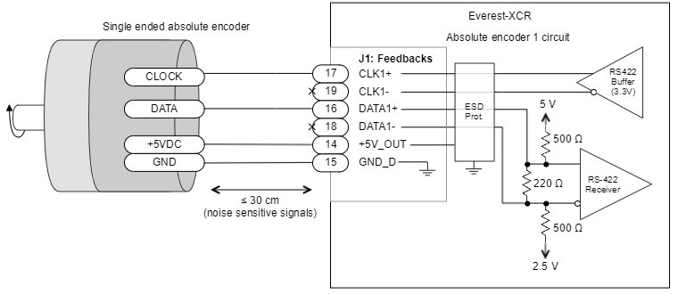
Next Figure shows how to connect a single SSI or BISS-C absolute encoder to the Everest XCR servo drive.
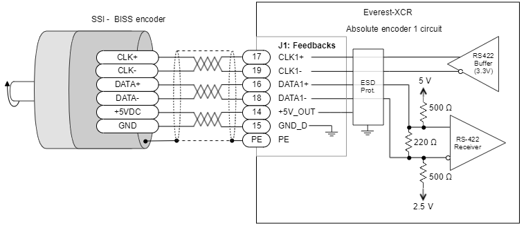
For single-ended devices, connect the positive pins of CLK+ and DATA+ and leave the other pins unconnected.
In the case that the encoder has a current consumption higher than 200 mA (maximum current output of the +5V_OUT pin of the Everest XCR) or that the encoder has an input supply > 5V, an external power supply will need to be used in order to power the encoder and in this case some wiring changes need to be taken into account (this applies to both the differential and single-ended encoders, both incremental and absolute):
- Data and clock connections remain the same between the encoder and the drive
- +5V_OUT pin of the drive is not connected
- The input voltage pin of the encoder is connected to the input voltage of the additional power supply
- The GND of the additional power supply is connected to both GND pins of the encoder and the drive in order to have a proper reference for the encoder signals
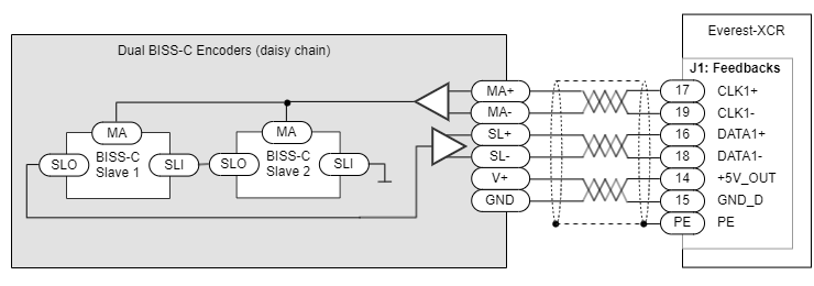
For dual daisy-chain BISS-C use the following connection. Dual BISS-C can be used for redundancy or to read the position of the rotor before and after a gearbox. Further details on this interface can be found here Primary Absolute Slave 2.
Absolute Encoder 2
The Absolute Encoder 2 interface can be used as a position, velocity and commutation feedback device. This feedback is shared with the incremental encoder input, so you will have to select which one is used by software.
Specification | Value |
|---|---|
Type of inputs | Differential / Single ended |
ESD capability | IEC 61000-4-2 (ESD) ± 30 kV (air), ± 30 kV (contact) IEC 61000-4-5; tp = 8/20 μs 12 A, 200 W |
| Maximum operating voltage range | -0.5 ~ 5.5 V |
| Operating frequency | 100 kHz to 10 MHz (user configurable) |
| Receiver hysteresis | min 50 mV typ 80 mV (DATA+ - DATA-) |
| Termination | 220 Ω differential on data line. Fail safe basing resistors of 1 kΩ, see drawings. |
| Fail safe bias resistors | ENC_x+ (positive input) 1 kΩ to 5 V ENC_x- (negative input) 1 kΩ to 2.5 V (equivalent) |
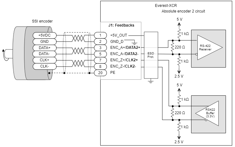
The next figure shows how to connect a secondary SSI absolute encoder to the Everest XCR servo drive.
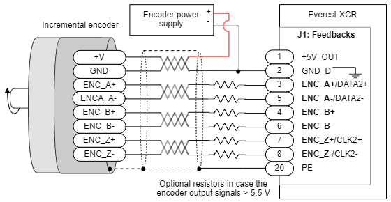
Incremental Encoder
Everest XCR can use single-ended or differential digital incremental encoder inputs (also known as quadrature incremental encoders) for velocity and/or position control, as well as for commutation purposes. The encoder provides incremental position feedback that can be extrapolated into precise velocity or position information. Using high-resolution encoders allows Everest XCR to perform sinusoidal commutation. Channel A and channel B signals should have a phase shift of 90 degrees, indicating the rotation direction. The drive has an optional index signal input. Index signal (Z) is a single pulse per revolution signal that can be used to know absolute positions and for homing operations. The following table illustrates the digital encoder inputs main features.
Specification | Value |
|---|---|
Type of inputs | Non-isolated |
Number of inputs | 3 (A, B and Index) |
ESD capability | IEC 61000-4-2 (ESD) ± 30 kV (air), ± 30 kV (contact) IEC 61000-4-5; tp = 8/20 μs 12 A, 200 W |
Maximum voltage range | -0.5 ~ 5.5 V |
| Maximum recommended working frequency | 10 MHz (differential) |
| Maximum readable pulse frequency | 50 MHz |
| Termination resistor | 220 Ω (between ENC_x+ and ENC_x-). |
| Fail safe bias resistors | ENC_x+ (positive input) 1 kΩ to 5 V ENC_x- (negative input) 1 kΩ to 2.5 V (equivalent) |
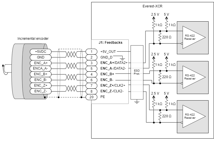
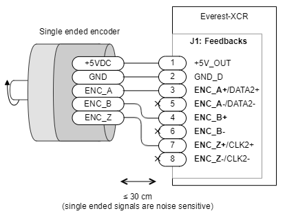
The wiring of a single-ended encoder to the Everest XCR is shown next:
Sometimes encoders require different supply voltages than 5 V or need more than the 200 mA provided by the drive. In those cases, the connection from the external power source should be as shown next:
Feedback wiring recommendations
Signal distortion and electrical noise is a common problem in feedback signals. These problems can result in a bad position or velocity calculation for both digital feedbacks (gain or loss of counts) and analog feedbacks (wrong voltage levels).To minimize these problems some wiring recommendations are shown:
- Use differential signals whenever is possible. That is, connect both positive and negative signals of differential feedback sensors. Use a twisted pair for each differential group of signals and another twisted pair for the +5 V supply and GND. Twisted-pairs help in the elimination of noise because disturbances induced in twisted pairs
- Twisted-pairs help in elimination of noise due to electromagnetic fields by twisting the two signal leads at regular intervals. Any induced disturbance in the wire will have the same magnitude and result in error cancellation.
- Connect the Everest XCR and encoder GND signals even if the encoder supply is not provided by the drive.
- The connection between Everest XCR PE and the motor metallic housing is essential to provide a low impedance path and minimize noise coupling to the feedback. For further information, see Protective Earth wiring.
- For better noise immunity, use shielded cables, with the shield connected to PE only in the drive side. Never use the shield as a conductor carrying a signal, for example as a ground line.
- It is essential to keep feedback wiring as far as possible from motor power, AC power and all other power wirings.