Safe Torque Off (STO)
The STO is a safety system that prevents motor torque in an emergency event while Everest XCR remains connected to the power supply. When STO is activated, the power stage is disabled by hardware and the drive power transistors are disconnected, no matter what control or firmware does. The motor shaft will slow down until it stops under inertia and frictional forces. Although not common, in the event of a failure of the power stage during an STO situation, the maximum expected motor movement with torque can be up to 180º electrical degrees. The system must be designed to avoid any hazard in this situation.
If the STO inputs are not energized or the wires are not connected, the transistors of the power stage are turned off and an STO fault is notified. In order to activate the power stage, and therefore allow the motor operation, the two STO inputs must be energized (high level, typically 5V to 24V). STO inputs should not be confused with a digital input configured as enable input, because enable input is firmware controlled and does not guarantee intrinsic safety as it can be reconfigured by a user.
In order to ensure redundancy and safety, the Everest XCR includes 2 separate STO inputs that must be activated or deactivated simultaneously (maximum 1.4 s mismatch). A difference of state between STO1 and STO2 inputs will be interpreted as an abnormal situation after 1.4 s the drive will be latched in a fault state. A power supply reset is necessary to remove this STO abnormal error.
Safety Function Specifications
Safety Function Specification | Value | |
|---|---|---|
Standards compliance |
| |
Safety function | Safe Torque Off (STO) | |
Safety relevant parameters according to EN 61508:2010 | Safety integrity level | SIL3 |
PFH | 1.34 x 10⁻⁹ 1/h | |
SFF | > 99 % (High) | |
Safety relevant parameters according to EN ISO 13849-1:2023 | PL | e |
Category | 3 | |
DC | 99% High | |
MTTFd | ≥ 100 years (High) | |
Safety Function Reaction Time | t < 6.3 ms The Safety Function Reaction time is measured as the time since one of the STO inputs (STO1 or STO2) goes below 1.1 V and the STO function actuates (power transistors deactivated). | |
Fault Reaction Time | t< 33 ms The worst-case fault reaction time is on the event of a 5V DC/DC supply overvoltage. | |
High-demand mode | The EUC (Equipment Under Control) is considered as a high-demand or continuous demand mode system. | |
Mission Time | The mission time of the EUC is of 20 years. | |
Diagnostic Time Interval | In order to guarantee the correct operation of the safety functions, the user has to check the STO function regularly, performing an STO External Diagnostic Test (see further information below). The diagnostic test interval is defined as a minimum of 1 activation per 3 months. | |
Integration Requirements
Functional Safety is only guaranteed within the following Integration Requirements.
Integration Requirement | Value | |
|---|---|---|
STO Interface electrical characteristics | Input pins | STO1, STO2 and STO_RET |
Number of independent channels | 2 | |
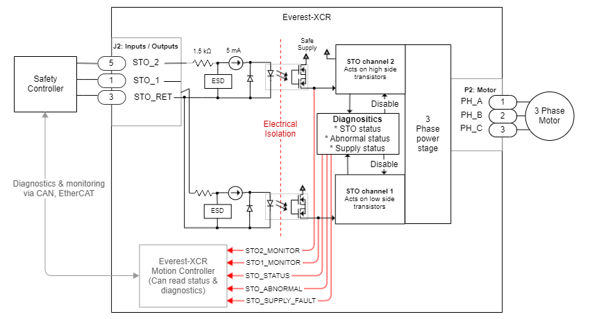
Type of Inputs | Isolated inputs (STO1, STO2) with common reference (STO_RET). ESD protected with input current limit to reduce power. See schematics next. | |
Maximum input LOW level (VIL) | 1.1 V or open (below this value the STO is ACTIVE, no torque can be applied to the motor) | |
Minimum Input HIGH level (VIH) | 3.6 V (above this value the STO input is inactive, torque can be applied to the motor) | |
Maximum absolute ratings | 24 V SELV (maximum OVP 26.4V (110%); maximum failure voltage 60 V) | |
Input current | 2.5 mA typ / 5 mA max per channel | |
Isolation Level | > 4 GΩ, 500 Vrms, 1000 VDC | |
ESD capability | IEC 61000-4-2 (ESD) ± 15 kV (air), ± 8 kV (contact), IEC 61000-4-4 (EFT) 40 A (5/50 ns), IEC 61000-4-5 (Surge) IPPM > 8 A | |
STO Interface timing characteristics | STO activation time (Safety function Reaction Time) | t < 6.3 ms |
STO deactivation time | t < 2ms | |
Minimum, non-detected STO short pulse | t < 400 µs The Safety controller can transmit short pulses to STOx inputs for diagnostics purposes. These pulses will be ignored by the safety circuit and will not stop the power stage. | |
Abnormal STO diagnostic time | ≤ 6.3 ms (Activation STO) | |
Abnormal STO latching time | 1.4 s ~ 3.4 s (Latching state, permanent activation of STO until power reset) | |
Power supply diagnostic time | 5 V over-voltage 33 ms, 5 V under-voltage 33 ms 3.3 V over-voltage 200 ns, 3.3 V under-voltage 8 ms | |
Logic Supply Voltage Range 1 | Logic supply must be provided to the system 24 V SELV (range from 8V to 26.4V; maximum failure voltage 60 V) | |
Power Supply Voltage Range 1 | 48 V SELV (range from 8V to 60V; maximum failure voltage 60 V) | |
Motor Type | STO safety function is only considered when the drive is controlling three-phase permanent magnet synchronous rotating motors. STO does not apply to DC brush motors. | |
Uncontrolled Motor Movement |
Uncontrolled Motor Movement In the event of a failure in the power stage, the motor shaft may rotate up to 180º electrical degrees. It is responsibility of the customer to prevent any hazards related ot this unexpected motor movement. | |
Environmental Conditions for STO2 | Pollution degree | Pollution degree 2 with an IP54 enclosure installation. |
Over-voltage category | II | |
Altitude | < 2000 m above sea level. | |
Operating Temperature | -20ºC to 50 ºC | |
Storage Temperature | -40ºC to 100ºC | |
Vibration | 5 Hz to 500 Hz, 4-5 g. Test according to IEC 60068-2-6:2007-12: Test Fc | |
Shock | ±15g Half-sine 11 msec Test according to IEC 60068-2-27:2008-02: Shock | |
Diagnostics | Internal power supply voltage monitors. Differences between STO1 and STO2 cause abnormal fault. After 1.4 s a hardware latching condition disables the drive until power cycling. Status of STO1, STO2, STO_REPORT, ABNORMAL_FAULT, and SUPPLY_FAULT can be read from the communications. STO firmware notification A STO stop is notified to the motion controller and creates a fault that can be read externally from any communication interface, however, STO operation is totally independent and decoupled from control or firmware. | |
EMC | Functional Safety has been tested according to IEC 61800-3:2018 procedures with the extended ranges of EN 61800-5-2:2017. To fulfill the EMC requirements it is necessary the use of the following elements is required:
| |
1: Although the drive can operate in a wider range of voltages as can be seen in Product Description, the system cannot be considered safe outside this range.
2: The drive can operate outside this range as indicated in the Product Description, however, the system cannot be considered safe as the system reliability and safety margins would not meet the standards.
STO External Diagnostic Test
The operation of the STO diagnostic circuits must be verified at least once per 3 months. The following procedure details a method to verify the STO diagnostic circuits and the external wiring. If the procedure results are not the expected ones, safety could be violated and the system cannot be used. Note that it is responsibility of the customer to prevent any hazards related to motor movement during this proof test.
The procedure requires the Everest XCR to be connected to a brushless motor.
Procedure Step | Action | Expected Result |
|---|---|---|
1 | Power on the Everest XCR with STO1 = low, STO2 = low. | - |
2 | Try to perform a "Motor Enable" (using Motionlab 3 or network commands). | Power stage is not enabled. Check it by software (a fault should appear) or by hardware (checking the Motor phases voltage with a multimeter). CAUTION: If power stage can be enabled, a problem on the diagnostics system or in teh wiring could exist. |
3 | Provide STO1 = high, STO2 = low. Remain in this state more than 3.4 seconds. | - |
4 | Try to perform a "Motor Enable" (using Motionlab 3 or network commands). | Power stage is not enabled. Check it by software (a fault should appear) or by hardware (checking the Motor phases voltage with a multimeter). CAUTION: If power stage can be enabled, a problem on the diagnostics system or in teh wiring could exist. |
5 | Provide STO1 = high, STO2 = high. | - |
6 | Try to perform a "Motor Enable" (using Motionlab 3 or network commands). | Power stage is not enabled. Check it by software (a fault should appear) or by hardware (checking the Motor phases voltage with a multimeter). CAUTION: If power stage can be enabled, a problem on the diagnostics system or in teh wiring could exist. |
7 | Shut-down Everest XCR supply and remain in this state for more than 10 seconds. | - |
8 | Power on the Everest XCR with STO1= low, STO2 = high. Remain in this state more than 3.4 seconds. | - |
9 | Try to perform a "Motor Enable" (using Motionlab 3 or network commands). | Power stage is not enabled. Check it by software (a fault should appear) or by hardware (checking the Motor phases voltage with a multimeter). CAUTION: If power stage can be enabled, a problem on the diagnostics system or in teh wiring could exist. |
10 | Provide STO1 = high, STO2 = high. | - |
11 | Try to perform a "Motor Enable" (using Motionlab 3 or network commands). | Power stage is not enabled. Check it by software (a fault should appear) or by hardware (checking the Motor phases voltage with a multimeter). CAUTION: If power stage can be enabled, a problem on the diagnostics system or in teh wiring could exist. |
12 | Shut-down Everest XCR supply and remain in this state for more than 10 seconds. | - |
13 | Power on the Everest XCR with STO1= high, STO2 = high. | - |
14 | Try to perform a "Motor Enable" (using Motionlab 3 or network commands). | Power stage can be enabled, allowing motor rotation. Check it by software (system should enter in motor enable state) or by hardware (checking the Motor phases voltage with a multimeter). If power stage cannot be enabled it could be caused by other faults not related with STO (over-voltage, under-voltage, etc.) |
STO Operation States
The truth table of the STO inputs is shown next indicating the different states of the system:
Mode | State | STO1 status / level | STO2 status / level | Power stage status | STO report bit status | STO abnormal fault | State description | ||
|---|---|---|---|---|---|---|---|---|---|
Normal operation | STO Enabled | 0 | < 1.1 V | 0 | < 1.1 V | OFF | 0 | 0 | The system logic is powered, but the STO function is activated. Therefore, no torque can be applied to the motor. STO trip is reported to the MCU and to the safety circuitry. This is intended safe torque off with dual-channel operation. |
Torque enabled (STO inactive) | 1 | > 3.6 V | 1 | > 3.6 V | Can be enabled | 1 | 0 | The STO function is deactivated, and torque can be provided to the motor. The motor can run under firmware control. This is the normal operation state. | |
Abnormal operation |
| 0 | < 1.1 V | 1 | > 3.6 V | OFF | 0 | 1 | If any issue is detected on the dual-channel STO function (their state is different for a long period of time), an abnormal fault is active can be reported. This state avoids the application of torque to the motor. If this persists for > 1.4 s ~ 3.4 s the STO will lock in FAULT state. To reset this fault a power cycle is needed. |
1 | > 3.6 V | 0 | < 1.1 V | OFF | 0 | 1 | |||
Abnormal STO Latched | x | - | x | - | OFF | NOR (STO1, STO2) | 1 | After >1.4 s ~ 3.4 s of abnormal STO active, the driver will stay in this state until the power supply cycle. | |
Abnormal Supply | x | x | x | x | OFF | x | x | If a voltage out of the limits is detected on the internal logic voltages, the system is conducted to a safe state, similar to power-off. Only if the safe logic voltages are recovered (usually after reparation or restart), the system can return to any other state. | |
Interface and Connections
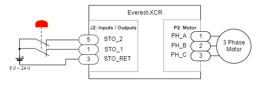
The wiring of the recommended STO circuit is shown next.
STO1 and STO2 signals should always change at the same time with a maximum of 1.4 s mismatch. This is necessary to have 2 channel redundancy and allow diagnostics, as a mismatch will cause an abnormal fault.
The logic level of an STO signal between 1.1V and 3.6V is unknown. If supplied at unknown level, STO1 and STO2 could have different logic values and trigger an abnormal latching fault.
In order to ensure this, do not add big capacitors (> 100 µF) in parallel to the STO inputs as this may cause faults during activation or deactivation of the STO.
Les signaux STO1 et STO2 doivent toujours changer en même temps avec un décalage maximum de 1,4 s. Ceci est nécessaire pour avoir une redondance à 2 canaux et permettre le diagnostic, car une discordance provoquera une anomalie de fonctionnement.
Afin de garantir cela, n'ajoutez pas de gros condensateurs (> 100 µF) en parallèle aux entrées STO, car cela pourrait provoquer des défauts lors de l'activation ou de la désactivation du STO.
Le niveau logique d'un signal STO entre 1,1 V et 3,6 V est inconnu. S'ils sont alimentés à un niveau inconnu, STO1 et STO2 peuvent avoir des valeurs logiques différentes et provoquer une anomalie de fonctionnement.
Wiring for a solution with panic button / emergency stop. When using this circuit ensure the difference between STO_1 and STO_2 signals changing the state is less than 1.4 s to prevent an abnormal situation. When using various protective switches connect them in series.