Product Description
Everest XCR is a high power, highly integrated, ready to use digital servo drive. The drive includes all the required interface electronics and connectors, features best-in-class energy efficiency thanks to its state of the art power stage, and can be easily configured with Ingenia's free software MotionLab 3.
Everest XCR is enabled with EtherCAT and CANopen communications.
Main features:
Ultra-small footprint
Up to 80 VDC, 45 A continuous
Up to 98% efficiency
Up to 50 kHz current loop, 25 kHz servo loops
10 kHz ~ 100 kHz PWM frequency
16 bit ADC with VGA for current sensing
Supports Halls, Quadrature encoder, SSI and BiSS-C
Up to 4 simultaneous feedback sources
Full voltage, current and temperature protections
Safety Torque Off (STO SIL3 Ple) inputs
Typical applications:
Collaborative robot joints
Robot end effectors
Robotic exoskeletons
Wearable robots
AGVs
UAVs
Industrial highly integrated servomotors
Smart motors
Battery-powered and e-Mobility
Low inductance motors
Part Numbering
Product | Ordering part number | Communications | Environment | Status | Image |
|---|---|---|---|---|---|
Everest XCR Ready-to-use servo drive featuring EtherCAT communications. | EVE-XCR-E | EtherCAT | Industrial | PRODUCTION | 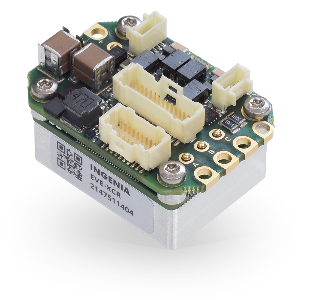 |
EVE-E-XCR-E | EtherCAT | Extended | PRODUCTION | ||
Everest XCR Ready-to-use servo drive featuring CANopen and Ethernet communications. | EVE-XCR-C | CANopen / Ethernet | Industrial | PRODUCTION | |
EVE-E-XCR-C | CANopen / Ethernet | Extended | PRODUCTION |
General Label Idendification |
|---|
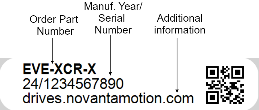 |
For applications requiring a pluggable drive enabled with EtherCAT or CANopen, please see Everest NET.
For applications not requiring CANopen or EtherCAT, please see Everest CORE.
Specifications
Electrical and Power Specifications
Part number → | Industrial (EVE-XCR-E / EVE-XCR-C) | Extended (EVE-E-XCR-E / EVE-E-XCR-C) | ||
|---|---|---|---|---|
Minimum power supply voltage | 8 VDC | |||
Maximum absolute power supply voltage | 80 VDC (continuous) 85 VDC (peak 100 ms) Working at 80 V will require a stable power supply able to absorb any possible reinjection coming back from the driver. | 52 VDC (continuous) | ||
Recommended power supply voltage | 12 VDC ~ 72 VDC This voltage range ensures a safety margin including power supply tolerances and regulation during acceleration and braking. | 12 VDC ~ 52 VDC | ||
Internal drive DC bus capacitance | 49 µF Note that EVE-XCR uses ceramic capacitors. The capacitance value varies with DC bias and temperature. | |||
Logic power supply voltage (optional) | 8 to 50 VDC Providing the logic supply is optional, as the drive is supplied from the DC bus (single supply) on its full operating voltage range. When supplied from logic, an intelligent switch will stop consuming from the DC bus. | |||
Boot-up time | 15 s | |||
Minimum shutdown time | 500 ms | |||
Maximum continuous phase current | 45 A @ 60 ºC Typically, 45 A can be obtained working at 48 V, 20 kHz with an appropriate cooling to keep case temperature under 60 ºC. On higher temperatures an automatic current derating will be applied to protect the system. See Thermal and Power Specifications below. | |||
Maximum peak phase current | 60 A @ 1 sec Notice that peak current could be limited by an automatic current derating algorithm. In order to get 60 A, case temperature should be kept below 35 ºC. | |||
Maximum continuous switch-off rectified current |
Notice that maximum current is dependent on temperature and heatsink attached. At higher temperature, the lower the current. For more information about heatsink applied, see Thermal and Power Specifications below. A continuous use of disabled power stage as rectifier is not recommended for thermal limitations. | |||
Maximum continuous output power | > 3 kW How the output power is calculated in an Ingenia drive. | |||
Efficiency | Up to 98.5% | |||
Maximum DC Bus voltage utilization | 99.73% @ 10 kHz 99.55% @ 20 kHz 99.04% @ 50 kHz 95.25% @ 100 kHz Note 1: these values assume a Sinusoidal commutation and no load connected. | |||
Standby logic supply consumption | 2.4 W ~ 3.2 W (for EtherCAT-enabled version) See details and conditions in the section below. | |||
Motion Control Specifications
Supported motor types |
| |||
|---|---|---|---|---|
Power stage PWM frequency (configurable) | 10 kHz, 20 kHz (default), 50 kHz & 100 kHz | |||
Current sensing | 3 phase, shunt-based current sensing. 16 bit ADC resolution. Accuracy is ±2% full scale. | |||
Current sense resolution (configurable) | Current gain is configurable in 4 ranges:
| |||
Current sense ranges (configurable) | Current ranges for the 4 configurable current gains:
| |||
Max. Current loop frequency (configurable) | 50 kHz Check the Power Stage & Control loops relationship section below. | |||
Max. servo loops frequency (position, velocity & commutation) (configurable) | 25 kHz Check the Power Stage & Control loops relationship section below. | |||
Feedbacks |
*Not all the existing absolute encoders are supported. Contact Ingenia for further information. | |||
Supported target sources | Network communication (EtherCAT / CANopen) | |||
Control modes |
| |||
Inputs/Outputs and Protections
General purpose Inputs and outputs | 4x non-isolated single-ended digital inputs - 5 V logic level & 3.3 V compatible. Can be configured as:
4x non-isolated single-ended digital outputs - 5 V logic level (continuous short circuit capable with 470 Ω series resistance) - 8 mA max. current. Can be configured as:
1x ±10 V, 16 bit, fully differential analog input for load cells or torque sensors. Can be read by the Master to close a torque loop. | |||
|---|---|---|---|---|
Shunt braking resistor output | Configurable over any of the digital outputs (see above). Enabling this function would require an external transistor or power driver. | |||
Motor brake output | 1 A, 50 V, dedicated brake output. Open drain with re-circulation diode. Brake enable and disable timing can be configured accurately. | |||
Safe Torque OFF inputs | 2x dedicated, isolated (> 4 GΩ, 1 kV) STO inputs (from 3.6 V to 24 V). The STO inputs include a current limiter at ~ 2.5 mA to minimize losses. Details: Safe Torque Off (STO). | |||
Motor temperature input | 1x dedicated, 5 V, 12-bit, single-ended analog input for motor temperature (1.65 kΩ pull-up to 5 V included). NTC, PTC, RTD, linear voltage sensors , silicon-based sensors and thermal switches are supported. | |||
Protections |
| |||
Communication for Operation
EtherCAT (EVE-XCR-E / EVE-E-XCR-E) | CANopen over EtherCAT (CoE) File over EtherCAT (FoE) Ethernet over EtherCAT (EoE) | |||
|---|---|---|---|---|
CANopen / Ethernet (EVE-XCR-C / EVE-E-XCR-C) | CiA-301, CiA-303, CiA-305, CiA-306 and CiA-402 (4.0) compliant. 125 kbps to 1 Mbps (default). Non-isolated. Termination resistor not included. Note: Ethernet ports can be used to configure the drive. | |||
Environmental Conditions
Part number → | Industrial (EVE-XCR-E / EVE-XCR-C) | Extended (EVE-E-XCR-E / EVE-E-XCR-C) | ||
|---|---|---|---|---|
Environmental test methods | IEC 60068-2 | MIL-STD-810G | ||
Case temperature (Operating) | -20 ºC to +85 ºC Check the Current Derating section below. | -40 ºC to +85 ºC Check the Current Derating section below. | ||
Case temperature (Non-Operating) | -40 ºC to +100 ºC | -50 ºC to +100 ºC | ||
Thermal Shock (Operating) | 25 ºC to 60 ºC in 25 min | -40 ºC to 70 ºC within 3 min | ||
Maximum Humidity (Operating) | up to 95%, non-condensing at 85 ºC | up to 95%, non-condensing at 85 ºC | ||
Maximum Humidity (Non-Operating) | up to 95%, non-condensing at 85 ºC | up to 95%, non-condensing at 85 ºC | ||
Altitude (Operating) | -400 m to 2000 m | -400 m to 10000 m | ||
Vibration (Operating) | 5 Hz to 500 Hz, 4-5 g | 20 Hz to 2000 Hz, 14.6 g | ||
Mechanical Shock (Operating) | ±15g Half-sine 11 msec | ±20g Half-sine 11 msec | ||
Mechanical Shock (Non-Operating) | ±15g Half-sine 11 msec | ±40g Half-sine 11 msec | ||
Pollution degree and installation environment | Pollution Degree 2 environment according to IEC 61800-5-1: Normally, only non-conductive pollution occurs. Occasionally, a temporary conductivity caused by condensation is to be expected when the Everest XCR is off. | |||
Minimum index of protection of the installation | IP3X: Since Everest XCR has accessible live electrical circuits, it should be installed on closed electrical operating areas with a minimum protection rating of IP3X and should be accessed by skilled or instructed persons. | |||
Reliability Specifications
Part number → | Industrial (EVE-XCR-E / EVE-XCR-C) | Extended (EVE-E-XCR-E / EVE-E-XCR-C) |
|---|---|---|
MTBF | > 360.000 h Based on FIDES method for Standard Life Profile at 40 °C average. Other scenarios available on demand. | > 90.000 h Based on FIDES method for "Equipment (in avionics bay) mounted in a medium haul civil aircraft" at 40 ºC average. Other scenarios available on demand. |
Isolation between aluminum case (PE) and live circuits | Basic insulation according to IEC 61800-5-1. > 200 MΩ. Measured between PE (case) and GND_P and +SUP and phases. Note: The drive includes 2 nF EMC capacitance between the power supply negative (GND_P) and the enclosure (PE). | |
Mechanical Specifications
Aluminum case | Yes (interface board not covered). Minimum wall thickness > 0.75 mm. | |||
|---|---|---|---|---|
Horizontal dimensions | 42 mm x 29 mm | |||
Height | 23.2 mm Dimensions include mating connectors | |||
Weight | 38 gr | |||
Compliance
Part number → | Industrial (EVE-XCR-E / EVE-XCR-C) | Extended (EVE-E-XCR-E / EVE-E-XCR-C) | ||
|---|---|---|---|---|
EC Directives | CE Marking
| |||
Low Voltage Directive |
| |||
Electromagnetic Compatibility (EMC) Standards |
| |||
Product Safety Standard |
| |||
Functional Safety Standard | Safe Torque Off (STO)
See Safe Torque Off (STO) section for mandatory Integration Requirements. | |||
Environmental Test methods | IEC 60068-2:
| MIL-STD-810G:
| ||
Product Revisions
Product | Revision | Date | Notes |
|---|---|---|---|
Everest XCR | 1 |
| Initial prototype |
Everest XCR | 2 |
| Second prototype. Known issues or pending features:
|
Everest XCR | 3 |
| Known issues or pending features:
|
Everest XCR | 4 |
| First official product release. |
Everest XCR | 5 |
|
|
Everest XCR | 6 |
| |
Everest XCR | 7 |
|
|
Everest XCR | 8 |
|
|
Everest XCR | A |
| Current version |
Everest XCR Extended | 10 |
| Current version |
Thermal and Power Specifications
Standby power consumption
The following table shows the standby power consumption of the Everest assuming 1 EtherCAT/Ethernet port is active and communicating at full speed, no feedbacks or I/Os are connected. When the power stage is enabled, motor current is set to 0 and housing temperature is kept at 50ºC.
Power supply voltage | Typical total standby power consumption with single supply | Power savings by having dual supply with logic at 12 V* | |||||
|---|---|---|---|---|---|---|---|
Power stage disabled | Power stage enabled and switching at 0 current | ||||||
EtherCAT (1 port active) | CANopen | 10 kHz | 20 kHz | 50 kHz | 100 kHz | ||
12 V | 2.50 W | TBD | 2.50 W | 2.54 W | 2.62 W | 2.74 W | ~0.0 W |
24 V | 2.60 W | 2.66 W | 2.72 W | 2.91 W | 3.24 W | ~0.10 W | |
48 V | 2.85 W | 3.07 W | 3.26 W | 3.80 W | 4.70 W | ~0.35 W | |
60 V | 2.94 W | 3.34 W | 3.61 W | 4.38 W | 5.66 W | ~0.44 W | |
72 V | 3.10 W | 3.34 W | 3.97 W | 5.00 W | 6.70 W | ~0.60 W | |
*If minimal standby power consumption is desired working at 48 V or higher it is suggested to have dual supply and provide 12 V or 24 V to the Logic. This reduces losses by allowing the main DC/DC converter to operate at peak efficiency.
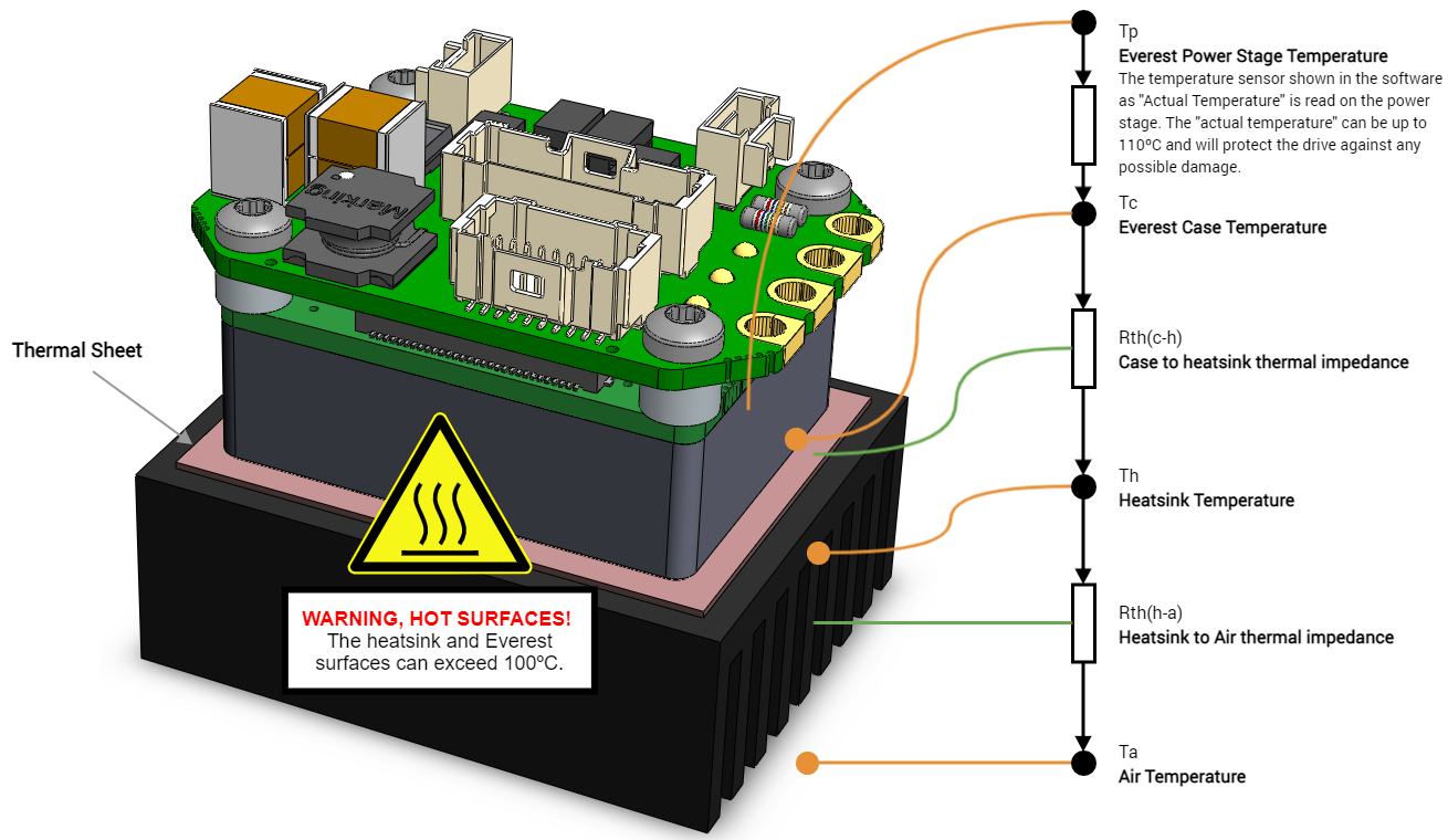
Thermal model
The following diagram depicts the general dissipation model. The Everest is designed to be mounted on a cooling plate or heatsink to achieve its maximum ratings. Please see Installation for more details. In order to calculate the heatsink requirements, the power dissipation can be estimated below.
In some low power applications, the Everest is NOT required to be mounted to any heatsink. In this case its thermal resistance from housing/case to ambient Rth(h-a) can be estimated between 8 K/W, to 12 K/W assuming 10 cm clearance to allow air convection at sea level. For example, with the drive on standby at 2.6 W losses at 25 ºC air temperature the internal drive temperature can be 56 ºC. When the Everest is not attached to a heatsink factors like air cooling, power cable thickness will have a significant effect on its temperature. Typically 7 W can be dissipated without heatsink, refer to the graph below to know which current can be handled.
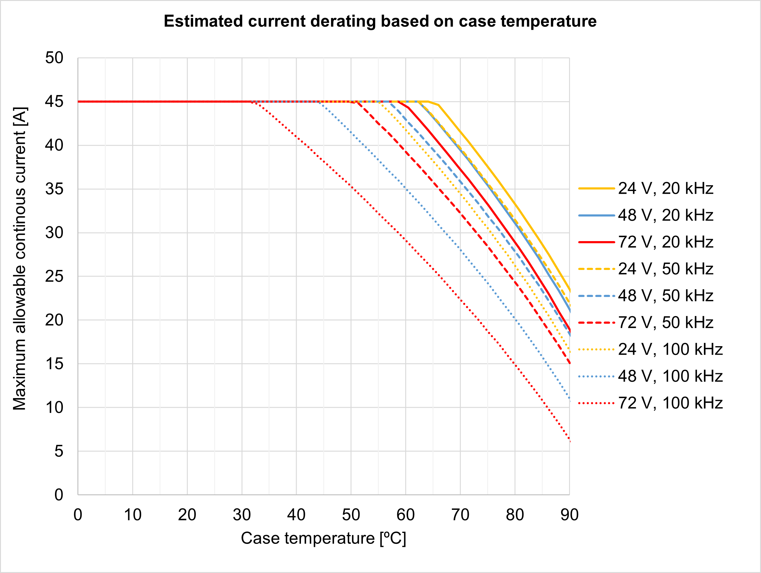
Current derating
The following figure show the maximum motor phase current at different case temperatures and operating points. As can be seen lower temperature, bus voltage or PWM frequency allows higher current due to lower heat dissipation. For highest current, Everest can be configured at 10 kHz PWM frequency, however this may not be suitable for low inductance motors or acoustic noise sensitive applications. The graph expresses the achievable current including the derating algorithm that limits the current based operation conditions and the power stage temperature.
Notice that current is expressed in crest value for a 3 phase BLAC motor. For further clarifications and conversion to equivalent RMS values please refer to Disambiguation on current values and naming for Ingenia Drives.
To ensure a proper performance of Everest XCR, the case temperature should be held always below 85 ºC (Tc-max = 85 ºC).
Heat dissipation and heatsink calculation
Following figure show the total power losses at different operating points. This includes logic supply and considers a single supply scenario. As can be seen, lower PWM frequency and voltage leads to lower power losses.
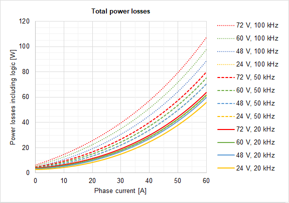
Please, use the following procedure to determine the required heatsink:
Based on the voltage & continuous (averaged) current required by your application and Current derating graph determine the Case temperature Tc. Remember that Case temperature must be always below 85 ºC (Tc < 85 ºC)
For example: If the application requires 30 A @ 72 V (20 kHz) the Tc will be 85 ºC
Based on the voltage & continuous current required by your application and Power losses graph determine the generated Power Losses PL to be dissipated.
For example: If the application requires 30 A @ 72 V (20 kHz) the PL will be 19 W
Determine the Thermal impedance of the used thermal sheet Rth(c-h)
For example, a thermal sheet TGX-150-150-0.5-0, which has an estimated thermal impedance of Rth(c-h) = 0.2 K/W
Based on the ambient temperature and using the following formula determine the maximum thermal impedance to air of the required heatsink Rth(h-a)
We don't have a way to export this macro.For example: If the application requires 30 A @ 72 V (20 kHz) working at Ta = 25 ºC and we use a thermal sheet with Rth(c-h) = 0.2 K/W the required thermal impedance of the heatsink will be Rth(h-a) = 3.35 K/W
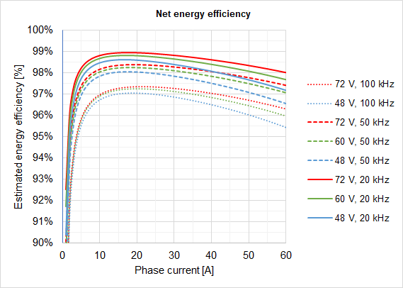
Energy efficiency
The following graph shows the electrical energy efficiency including logic for various operation points assuming 50 ºC case temperature and the drive delivering the maximum output power (i.e. maximum output voltage and motor speed). As seen, very high efficiencies > 99% can be achieved at 10 kHz or 20 kHz PWM frequencies.
Power Stage & Control loops relationship
The power stage PWM frequency can be adjusted in 4 different frequencies. Each frequency has an associated rate for the control loops, as specified in the following table.
Power stage PWM frequency | Current loop frequency | Servo loops frequency (position, velocity, commutation & shunt) |
|---|---|---|
10 kHz | 10 kHz | 10 kHz |
20 kHz | 20 kHz | 20 kHz |
50 kHz | 50 kHz | 25 kHz |
100 kHz | 50 kHz | 25 kHz |